Page 114 of 4592
AUTOMATIC TRANSAXLE UNIT
1913 Author�: Date�:
14. REMOVE EXHAUST MANIFOLD STAY
Remove the 2 bolts and exhaust manifold stay.
Torque: 42 N´m (")
Q10058
Q10059
Q00251
AX±20
± AUTOMATIC TRANSAXLE (A140E)AUTOMATIC TRANSAXLE UNIT
1913 Author�: Date�:
14. REMOVE EXHAUST MANIFOLD STAY
Remove the 2 bolts and exhaust manifold stay.
Torque: 42 N´m (430 kgf´cm, 31 ft´lbf)
15. REMOVE TRANSAXLE±TO±ENGINE BOLT
Torque: 66 N´m (670 kgf´cm, 48 ft´lbf)
16. REMOVE ENGINE HOOD
(a) Disconnect the washer pipe.
(b) Remove the 4 bolts and engine hood.
Torque: 14 N´m (145 kgf´cm, 10 ft´lbf)
17. RAISE AND SUPPORT VEHICLE SECURELY
18. REMOVE FRONT WHEELS
Torque: 103 N´m (1,050 kgf´cm, 76 ft´lbf)
19. REMOVE ENGINE UNDER COVER AND CENTER EN-
GINE UNDER COVER
20. DISCONNECT SHIFT CONTROL CABLE
(a) Remove the nut and disconnect the shift control cable
from the park/neutral position switch.
Torque: 15 N´m (150 kgf´cm, 11 ft´lbf)
(b) Remove the clip and disconnect the shift control cable
from the bracket.
21. REMOVE DIFFERENTIAL FLUID DRAIN PLUG AND
GASKET
HINT:
At the time of installation, please refer to the following item.
Replace the used gasket with a new gasket.
22. DRAIN DIFFERENTIAL FLUID
23. REMOVE LH AND RH FENDER APRON SEALS
24. REMOVE LH AND RH DRIVE SHAFTS
(See page SA±17)
Page 145 of 4592
AUTOMATIC TRANSAXLE UNIT
1944 Author�: Date�:
12. REMOVE 2 FRONT SIDE ENGINE MOUNTING BOLTS
Torque:
TMC Made: 80 N´m (820 kgf´cm, 59")
Q06478
Q10286
Q06530
Q10038
AX±24
± AUTOMATIC TRANSAXLE (A541E)AUTOMATIC TRANSAXLE UNIT
1944 Author�: Date�:
12. REMOVE 2 FRONT SIDE ENGINE MOUNTING BOLTS
Torque:
TMC Made: 80 N´m (820 kgf´cm, 59 ft´lbf)
TMMK Made:
Green color bolt: 66 N´m (670 kgf´cm, 48 ft´lbf)
Silver color bolt: 44 N´m (440 kgf´cm, 32 ft´lbf)
13. REMOVE STARTER AND A/T SHIFT CABLE CLAMP
(a) Disconnect the connector and remove the nut.
(b) Remove the 2 bolts, starter and A/T shift cable clamp.
Torque: 39 N´m (400 kgf´cm, 29 ft´lbf)
14. REMOVE EXHAUST MANIFOLD BRACKET MOUNT-
ING BOLT
Torque:
Except California: 20 N´m (200 kgf´cm, 15 ft´lbf)
California: 34 N´m (350 kgf´cm, 25 ft´lbf)
15. REMOVE 5 TRANSAXLE±TO±ENGINE BOLTS AND
DISCONNECT GROUND TERMINAL
Torque: 66 N´m (670 kgf´cm, 48 ft´lbf)
16. REMOVE ENGINE HOOD
(a) Disconnect the washer pipe.
(b) Remove the 4 bolts and engine hood.
Torque: 26 N´m (265 kgf´cm, 19 ft´lbf)
17. RAISE AND SUPPORT VEHICLE SECURELY
18. REMOVE FRONT WHEELS
Torque: 103 N´m (1,050 kgf´cm, 76 ft´lbf)
19. REMOVE DIFFERENTIAL FLUID DRAIN PLUG AND
GASKET
HINT:
At the time of installation, please refer to the following item.
Replace the used gasket with a new gasket.
20. DRAIN DIFFERENTIAL FLUID
21. REMOVE LH AND RH ENGINE SIDE COVERS
22. REMOVE LH AND RH FRONT DRIVE SHAFTS
(See page SA±25)
Page 157 of 4592
 Precoated parts are indicated in the component il-
lustrations by the º�º symbol.
7")
INTRODUCTIONGENERAL REPAIR INSTRUCTIONS ±
IN±5
the specified seal lock adhesive to the bolt, nut or
threads.
(c) Precoated parts are indicated in the component il-
lustrations by the º�º symbol.
7. When necessary, use a sealer on gaskets to prevent
leaks.
8. Carefully observe all specifications for bolt tightening
torques. Always use a torque wrench.
9. Use of special service tools (SST) and special service ma-
terials (SSM) may be required, depending on the nature
of the repair. Be sure to use SST and SSM where speci-
fied and follow the proper work procedure. A list of SST
and SSM can be found at the preparation of AX section.
10. When replacing fuses, be sure the new fuse has the cor-
rect amperage rating. DO NOT exceed the rating or use
one with a lower rating.
11. To pull apart electrical connectors, pull on the connector
itself, not the wires.
12. Care must be taken when jacking up and supporting the
vehicle. Be sure to lift and support the vehicle at the prop-
er locations.
(a) If the vehicle is to be jacked up only at the front or
rear end, be sure to block the wheels at the opposite
end in order to ensure safety.
(b) After the vehicle is jacked up, be sure to support it on
stands. It is extremely dangerous to do any work on
a vehicle raised on a jack alone, even for a small job
that can be finished quickly.
Page 300 of 4592
 Precoated parts are indicated in the component il-
lustrations by the º�º symbol.
7")
INTRODUCTIONGENERAL REPAIR INSTRUCTIONS ±
IN±5
the specified seal lock adhesive to the bolt, nut or
threads.
(c) Precoated parts are indicated in the component il-
lustrations by the º�º symbol.
7. When necessary, use a sealer on gaskets to prevent
leaks.
8. Carefully observe all specifications for bolt tightening
torques. Always use a torque wrench.
9. Use of special service tools (SST) and special service ma-
terials (SSM) may be required, depending on the nature
of the repair. Be sure to use SST and SSM where speci-
fied and follow the proper work procedure. A list of SST
and SSM can be found at the preparation of AX section.
10. When replacing fuses, be sure the new fuse has the cor-
rect amperage rating. DO NOT exceed the rating or use
one with a lower rating.
11. To pull apart electrical connectors, pull on the connector
itself, not the wires.
12. Care must be taken when jacking up and supporting the
vehicle. Be sure to lift and support the vehicle at the prop-
er locations.
(a) If the vehicle is to be jacked up only at the front or
rear end, be sure to block the wheels at the opposite
end in order to ensure safety.
(b) After the vehicle is jacked up, be sure to support it on
stands. It is extremely dangerous to do any work on
a vehicle raised on a jack alone, even for a small job
that can be finished quickly.
Page 443 of 4592
 Precoated parts are indicated in the component il-
lustrations by the º�º symbol.
7")
INTRODUCTIONGENERAL REPAIR INSTRUCTIONS ±
IN±5
the specified seal lock adhesive to the bolt, nut or
threads.
(c) Precoated parts are indicated in the component il-
lustrations by the º�º symbol.
7. When necessary, use a sealer on gaskets to prevent
leaks.
8. Carefully observe all specifications for bolt tightening
torques. Always use a torque wrench.
9. Use of special service tools (SST) and special service ma-
terials (SSM) may be required, depending on the nature
of the repair. Be sure to use SST and SSM where speci-
fied and follow the proper work procedure. A list of SST
and SSM can be found at the preparation of AX section.
10. When replacing fuses, be sure the new fuse has the cor-
rect amperage rating. DO NOT exceed the rating or use
one with a lower rating.
11. To pull apart electrical connectors, pull on the connector
itself, not the wires.
12. Care must be taken when jacking up and supporting the
vehicle. Be sure to lift and support the vehicle at the prop-
er locations.
(a) If the vehicle is to be jacked up only at the front or
rear end, be sure to block the wheels at the opposite
end in order to ensure safety.
(b) After the vehicle is jacked up, be sure to support it on
stands. It is extremely dangerous to do any work on
a vehicle raised on a jack alone, even for a small job
that can be finished quickly.
Page 992 of 4592

BO2DP±01
H09251
H09252
BO±6
± BODYLUGGAGE COMPARTMENT DOOR AND HINGE
REMOVAL
1. REMOVE LUGGAGE COMPARTMENT DOOR COVER
Remove the 11 clips and luggage compartment door cover.
2. REMOVE LUGGAGE COMPARTMENT DOOR
(a) Disconnect the connectors.
(b) Using a clip remover, disconnect the clamps.
(c) Remove the 4 bolts and door.
Torque: 7.8 N´m (80 kgf´cm, 69 in.´lbf)
3. REMOVE LUGGAGE COMPARTMENT TRIM FRONT
COVER
Using a clip remover, remove the 6 clips and luggage compart-
ment trim front cover.
4. REMOVE SPARE WHEEL COVER
5. REMOVE INNER LUGGAGE COMPARTMENT TRIM
COVER
(a) Using a clip remover, remove the 2 clips and inner lug-
gage compartment trim cover.
(b) Employ the same manner described above to the other
side.
6. REMOVE REAR FLOOR FINISH SIDE PLATES
Using a clip remover, remove the 6 clips and 2 rear floor finish
side plates.
7. REMOVE INNER LOWER LUGGAGE COMPARTMENT
TRIM COVER
(a) Remove the spare wheel carrier, spare wheel carrier
spacer and spare wheel.
(b) Using a clip remover, remove the 3 clips and inner lower
luggage compartment trim cover.
HINT:
Tape the screwdriver tip before use.
Page 1037 of 4592
 1MZ±FE engine:
Install a pad wear indicator plate on the inner pad.
(b) Apply disc brake grease to both sides of the inner anti±")
R00595
R02981
± BRAKEFRONT BRAKE PAD
BR±23
2046 Author�: Date�:
(a) 1MZ±FE engine:
Install a pad wear indicator plate on the inner pad.
(b) Apply disc brake grease to both sides of the inner anti±
squeal shims (See page BR±21).
(c) Install the 2 anti±squeal shims on each pad.
(d) Install inner pad with the pad wear indicator plate facing
upward.
(e) Install inner pad.
(f) Install outer pad.
NOTICE:
There should be no oil or grease adhering to the friction
surfaces of the pads or the disc.
(g) 5S±FE engine:
Install the 2 anti±squeal springs.
13. INSTALL CALIPER
(a) Draw out a small amount of brake fluid from the reservoir.
(b) Press in the piston with a hammer handle or similar imple-
ment.
HINT:
If the piston is difficult to push in, loosen the bleeder plug and
push in the piston while letting some brake fluid escape.
(c) Install the caliper.
(d) 5S±FE engine:
Hold the sliding pin and torque the installation bolt.
(e) 1MZ±FE engine:
Install the installation bolt.
Torque: 34 N´m (350 kgf´cm, 25 ft´lbf)
(f) Install the flexible hose and bolt to the bracket.
Torque: 29 N´m (300 kgf´cm, 21 ft´lbf)
14. INSTALL FRONT WHEEL
Torque: 103 N´m (1,050 kgf´cm, 76 ft´lbf)
15. DEPRESS BRAKE PEDAL SEVERAL TIMES
16. CHECK THAT FLUID LEVEL IS AT MAX LINE
Page 1040 of 4592
BR0AR±03
R02840
BR±26
± BRAKEFRONT BRAKE CALIPER
2049 Author�: Date�:
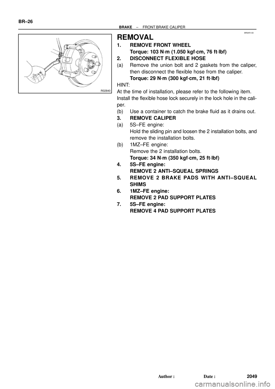
REMOVAL
1. REMOVE FRONT WHEEL
Torque: 103 N´m (1.050 kgf´cm, 76 ft´lbf)
2. DISCONNECT FLEXIBLE HOSE
(a) Remove the union bolt and 2 gaskets from the caliper,
then disconnect the flexible hose from the caliper.
Torque: 29 N´m (300 kgf´cm, 21 ft´lbf)
HINT:
At the time of installation, please refer to the following item.
Install the flexible hose lock securely in the lock hole in the cali-
per.
(b) Use a container to catch the brake fluid as it drains out.
3. REMOVE CALIPER
(a) 5S±FE engine:
Hold the sliding pin and loosen the 2 installation bolts, and
remove the installation bolts.
(b) 1MZ±FE engine:
Remove the 2 installation bolts.
Torque: 34 N´m (350 kgf´cm, 25 ft´lbf)
4. 5S±FE engine:
REMOVE 2 ANTI±SQUEAL SPRINGS
5. REMOVE 2 BRAKE PADS WITH ANTI±SQUEAL
SHIMS
6. 1MZ±FE engine:
REMOVE 2 PAD SUPPORT PLATES
7. 5S±FE engine:
REMOVE 4 PAD SUPPORT PLATES