Page 2626 of 4592
ENGINE UNIT
EM±75
1247 Author�: Date�:
INSTALLATION
1. INSTALL NO.1 REAR END PLATE
Install the")
EM08G±04
EM7333
Z18989
M/T
1
3
5
8
2 4 67
S05531
Wire
Bracket
Ground
Strap
± ENGINE MECHANICAL (5S±FE)ENGINE UNIT
EM±75
1247 Author�: Date�:
INSTALLATION
1. INSTALL NO.1 REAR END PLATE
Install the end plate with the bolt.
Torque: 9.3 N´m (95 kgf´cm, 82 in.´lbf)
2. M/T:
INSTALL FLYWHEEL
(a) Apply adhesive to 2 or 3 threads of the bolt end.
Adhesive:
Part No. 08833±00070, THREE BOND 1324 or equiva-
lent
(b) Install the flywheel on the crankshaft.
(c) Install and uniformly tighten the 8 bolts in several passes,
in the sequence shown.
Torque: 88 N´m (900 kgf´cm, 65 ft´lbf)
3. A/T:
INSTALL DRIVE PLATE (See step 2)
Torque: 83 N´m (850 kgf´cm, 61 ft´lbf)
4. M/T:
INSTALL CLUTCH DISC AND COVER
5. A/T:
CHECK TORQUE CONVERTER CLUTCH INSTALLA-
TION (A140E: See page AX±25)
6. INSTALL TRANSAXLE TO ENGINE
(a) Attach the transaxle to the engine.
(b) Install the ground strap, wire bracket and 4 bolts.
Torque:
46 N´m (470 kgf´cm, 34 ft´lbf) for 14 mm head
64 N´m (650 kgf´cm, 47 ft´lbf) for 17 mm head
Page 2775 of 4592
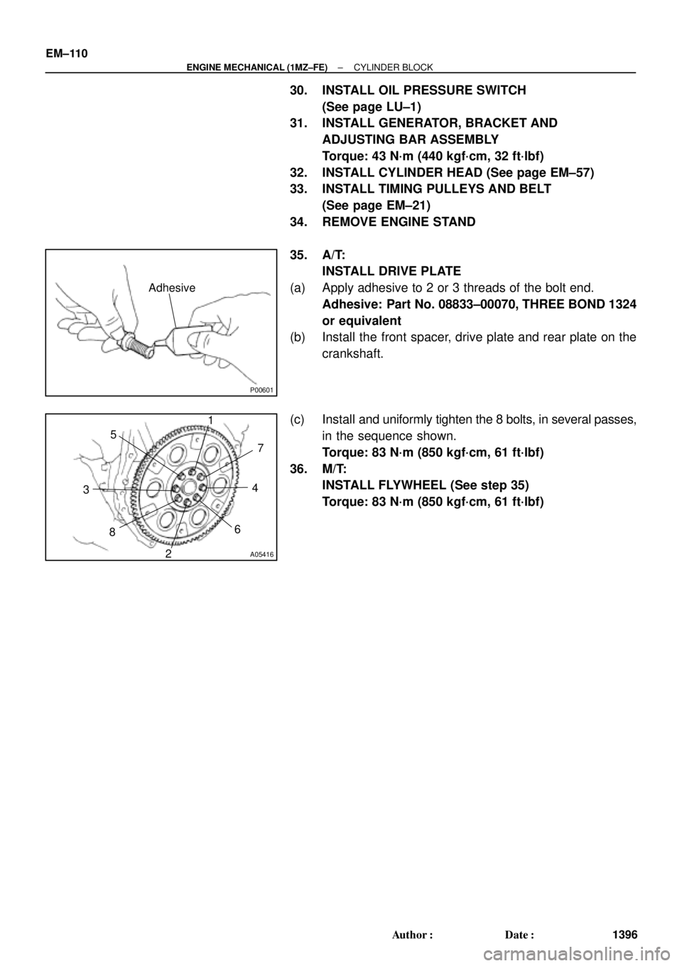
P00601
Adhesive
A05416
1
2 34 5
67
8
EM±110
± ENGINE MECHANICAL (1MZ±FE)CYLINDER BLOCK
1396 Author�: Date�:
30. INSTALL OIL PRESSURE SWITCH
(See page LU±1)
31. INSTALL GENERATOR, BRACKET AND
ADJUSTING BAR ASSEMBLY
Torque: 43 N´m (440 kgf´cm, 32 ft´lbf)
32. INSTALL CYLINDER HEAD (See page EM±57)
33. INSTALL TIMING PULLEYS AND BELT
(See page EM±21)
34. REMOVE ENGINE STAND
35. A/T:
INSTALL DRIVE PLATE
(a) Apply adhesive to 2 or 3 threads of the bolt end.
Adhesive: Part No. 08833±00070, THREE BOND 1324
or equivalent
(b) Install the front spacer, drive plate and rear plate on the
crankshaft.
(c) Install and uniformly tighten the 8 bolts, in several passes,
in the sequence shown.
Torque: 83 N´m (850 kgf´cm, 61 ft´lbf)
36. M/T:
INSTALL FLYWHEEL (See step 35)
Torque: 83 N´m (850 kgf´cm, 61 ft´lbf)
Page 2922 of 4592
OIL PUMP
LU±17
1681 Author�: Date�:
(b) Appl")
B04402
A Region ºXºRegion ºYº
A
CB B
C
Seal Width
Type A: 4 ± 5 mm
Type B: 3 ± 4 mmRegion ºXºRegion ºYº
AC Type A
Type B
± LUBRICATION (1MZ±FE)OIL PUMP
LU±17
1681 Author�: Date�:
(b) Apply seal packing to the oil pan as shown in the illustra-
tion.
Seal packing: Part No. 08826±00080 or equivalent
Region ºXº is at the outer side of the bolt hole.
Region ºYº is at the inner side of the bolt hole.
�Install a nozzle that has been cut to a 4 ± 5 mm (0.16
± 0.20 in.) (Type A) or 3 ± 4 mm (0.12 ± 0.16 in.)
(Type B) opening.
HINT:
Avoid applying an excessive amount to the surface.
�Parts must be assembled within 3 minutes of ap-
plication. Otherwise the material must be removed
and reapplied.
�Immediately remove nozzle from the tube and rein-
stall cap.
(c) Install the oil pan with the 19 bolts (or 17 bolts and 2 nuts).
Uniformly tighten the bolts and nuts in several passes.
Torque:
10 mm head: 8 N´m (80 kgf´cm, 69 in.´lbf)
12 mm head: 19.5 N´m (200 kgf´cm, 14 ft´lbf)
14 mm head: 37.2 N´m (380 kgf´cm, 27 ft´lbf)
(d) Install the flywheel housing under cover and exhaust pipe
support stay with the 2 bolts.
Torque: 7.8 N´m (80 kgf´cm, 69 in.´lbf)
5. INSTALL OIL STRAINER
Install a new gasket and the oil strainer with the bolt and 2 nuts.
Torque: 8 N´m (80 kgf´cm, 69 in.´lbf)
6. INSTALL NO.2 OIL PAN
(a) Remove any old packing (FIPG) material and be careful
not to drop any oil on the contact surface of the No.1 and
No.2 oil pans.
�Using a razor blade and gasket scraper, remove all
the old packing (FIPG) material from the gasket sur-
faces and sealing grooves.
�Thoroughly clean all components to remove all the
loose material.
�Using a non±residue solvent, clean both sealing
surfaces.
NOTICE:
Do not use a solvent which will affect the painted surfaces.
Page 2923 of 4592
OIL PUMP
1682 Author�: Date�:
(b) Apply seal packing to the No.2 oil pan as shown in the il-
lustration.
Seal packing:
Part No. 08826�")
P12568
A
A
BB
Seal Width
4 ± 5 mm LU±18
± LUBRICATION (1MZ±FE)OIL PUMP
1682 Author�: Date�:
(b) Apply seal packing to the No.2 oil pan as shown in the il-
lustration.
Seal packing:
Part No. 08826±00080 or equivalent
�Install a nozzle that has been cut to a 4 ± 5 mm (0.16
± 0.20 in.) opening.
HINT:
Avoid applying an excessive amount to the surface.
�Parts must be assembled within 3 minutes of ap-
plication. Otherwise the material must be removed
and reapplied.
�Immediately remove nozzle from the tube and rein-
stall cap.
(c) Install the No.2 oil pan with the 10 bolts and 2 nuts. Uni-
formly tighten the bolts and nuts in several passes.
Torque: 8 N´m (80 kgf´cm, 69 in.´lbf)
7. INSTALL A/C COMPRESSOR HOUSING BRACKET
Torque: 25 N´m (250 kgf´cm, 18 ft´lbf)
8. INSTALL NO.3 TIMING BELT COVER
(See page EM±21)
9. INSTALL TIMING PULLEYS (See page EM±21)
10. INSTALL TIMING BELT (See page EM±21)
11. INSTALL ADJUSTING STRUT AND PS PUMP DRIVE
BELT
(a) Temporarily install the adjusting strut with the bolt and the
nut.
(b) Install the drive belt with the pivot and adjusting bolts.
Torque: 43.1 N´m (440 kgf´cm, 32 ft´lbf)
(c) Tighten the nut.
Torque: 43.1 N´m (440 kgf´cm, 32 ft´lbf)
12. INSTALL A/C COMPRESSOR (See page AC±47)
13. INSTALL GENERATOR DRIVE BELT
(See page CH±16)
14. INSTALL FRONT EXHAUST PIPE BRACKET TO
NO.1 OIL PAN
Torque: 21 N´m (210 kgf´cm, 15 ft´lbf)
15. INSTALL FRONT EXHAUST PIPE (See page EM±76)
16. REMOVE RH FENDER APRON SEAL
17. REMOVE RH FRONT WHEEL
18. FILL ENGINE WITH OIL
19. START ENGINE AND CHECK FOR LEAKS
20. RECHECK ENGINE OIL LEVEL
Page 2936 of 4592

w/ Cruise Control :
Cruise Control Actuator
12 (120, 9)
Clutch Line Bracket
21 (210, 15)
12 (120, 9)
Clutch Release Cylinder
26 (270, 20)
RH Drive Shaft�
�32 (330, 2")
MX04Z±01
Q09981
Hood
14 (150, 10)
w/ Cruise Control :
Cruise Control Actuator
12 (120, 9)
Clutch Line Bracket
21 (210, 15)
12 (120, 9)
Clutch Release Cylinder
26 (270, 20)
RH Drive Shaft�
�32 (330, 24)
7.8 (80, 69 in.´lbf)
Flywheel Housing Under CoverRH Fender
Apron SealClutch Accumulator
Vehicle Speed Sensor
Connector
46 (470, 34)
Engine LH Mounting
Insulator with Bracket
Rear RH Suspension Member Brace
37 (380, 27)
Transaxle
64 (650, 47)
36 (370, 27)
10 (100, 7)
Steering Return Pipe
19 (195, 14)
32 (330, 24)
181 (1,850, 134)
Silver Bolt : 44 (450, 33)
Green Bolt : 66 (670, 48)
Suspension Member with
Lower Suspension Arm
Front RH Suspension
Member Brace
181 (1,850, 134)
Control
Cable
Clip13 (130, 9)
Clip
Washer
Starter
21 (210, 15)
39 (400, 29)
Air Cleaner
Case Assembly
with Air Hose
64 (650, 47)Ground Cable
x5Back±Up Light Switch Connector
Engine Wire
20 (200, 14)Hold±Down
Clamp
Battery
LH Drive Shaft
LH Fender Apron Seal RH Exhaust Manifold Stay
64 (650, 47)
181 (1,850, 134)PS Gear Assembly
No.1 Fuel Tube Protector
49 (500, 36)
294 (3,000, 217)
Lock Cap
Rear LH Suspension Member Brace
Stabilizer Bar Link
Hole
Plug
127 (1,300, 94)
39 (400, 29)
80 (820, 59)48 (490, 35)
Silver Bolt : 44 (450, 33)
Green Bolt : 66 (670, 48)
Front LH Suspension
Member Brace RH Fender
Liner
Engine Rear Side
Shutter Plate
56 (570, 41)
�
�
62 (630, 46) �
62 (630, 46) �
Front Exhaust Pipe
No.1 Exhaust Pipe
Support Bracket
33 (330, 24)
Exhaust Pipe Support Stay
33 (330, 24)LH Fender
Liner
66 (670, 48)
Snap Ring
�Snap Ring
�Cotter Pin
�Cotter Pin
�Gasket
�Gasket
�Gasket
Non±reusable part: Specified torque
N´m (kgf´cm, ft´lbf)
�
36 (370, 27)
± MANUAL TRANSAXLE (E153)MANUAL TRANSAXLE UNIT
MX±3
1804 Author�: Date�:
MANUAL TRANSAXLE UNIT
COMPONENTS
Page 2938 of 4592
MANUAL TRANSAXLE UNIT
MX±5
1806 Author�: Date�:
10. REMOVE 5 TRANSAXLE UPPER SIDE MOUNTING
BOLTS
Torque:
17 m")
Q09986
Q09987
Filler Plug
Oil Level
0 ± 5 mm
Drain Plug
Q09988
± MANUAL TRANSAXLE (E153)MANUAL TRANSAXLE UNIT
MX±5
1806 Author�: Date�:
10. REMOVE 5 TRANSAXLE UPPER SIDE MOUNTING
BOLTS
Torque:
17 mm head: 64 N´m (650 kgf´cm, 47 ft´lbf)
11. REMOVE FRONT WHEEL
Torque: 103 N´m (1,050 kgf´cm, 76 ft´lbf)
12. RAISE VEHICLE
NOTICE:
Make sure that the vehicle is securely supported.
13. REMOVE ENGINE REAR SIDE SHUTTER PLATE AND
LH AND RH FENDER APRON SEALS
14. DRAIN TRANSAXLE OIL
Oil grade: API GL±4 or GL±5
Viscosity: SAE 75W±90
Capacity: 4.2 liters (4.4 US qts, 3.7 Imp. qts)
Torque: 49 N´m (500 kgf´cm, 36 ft´lbf)
15. REMOVE LH AND RH DRIVE SHAFTS
(See page SA±25)
16. REMOVE FRONT EXHAUST PIPE
(a) Remove the 2 bolts and exhaust pipe support stay.
Torque: 33 N´m (330 kgf´cm, 24 ft´lbf)
(b) Remove the 4 nuts and 2 gaskets from the exhaust man-
ifold.
Torque: 62 N´m (630 kgf´cm, 46 ft´lbf)
(c) Remove the 2 bolts, nuts and gasket.
Torque: 56 N´m (570 kgf´cm, 41 ft´lbf)
(d) Remove the 2 set bolts of the No.1 exhaust pipe support
bracket.
Torque: 33 N´m (330 kgf´cm, 24 ft´lbf)
(e) Remove the front exhaust pipe.
Page 2940 of 4592
MANUAL TRANSAXLE UNIT
MX±7
1808 Author�: Date�:
21. REMOVE LH ENGINE MOUNTING INSULATOR WIT")
Q09994
Q09995
Q09996
CA
C
A
CB
AAB
C
Q09997
14 mm Head B14 mm Head B
14 mm Head A
± MANUAL TRANSAXLE (E153)MANUAL TRANSAXLE UNIT
MX±7
1808 Author�: Date�:
21. REMOVE LH ENGINE MOUNTING INSULATOR WITH
BRACKET
(a) Remove the 2 hole plugs, nuts and 3 bolts.
Torque:
Bolt: 64 N´m (650 kgf´cm, 47 ft´lbf)
Nut: 80 N´m (820 kgf´cm, 59 ft´lbf)
(b) Lift up the transaxle and remove the left engine mounting
insulator with the bracket.
22. REMOVE HOLE PLUG AND 4 ENGINE REAR SIDE
MOUNTING NUTS
Torque: 66 N´m (670 kgf´cm, 48 ft´lbf)
23. ATTACH ENGINE SLING DEVICE TO ENGINE HANG-
ER
(See page EM±69)
24. DISCONNECT STEERING RETURN PIPE FROM
FRONT SUSPENSION MEMBER
Remove the 2 bolts.
Torque: 10 N´m (100 kgf´cm, 7 ft´lbf)
25. REMOVE FRONT SUSPENSION MEMBER WITH LOW-
ER SUSPENSION ARM
(a) Remove the LH and RH fender liner set screws.
(b) Remove the 6 bolts, 4 nuts, front LH and RH suspension
member braces, rear LH and RH suspension member
braces and front suspension member with the lower sus-
pension arm.
Torque:
Bolt A: 181 N´m (1,850 kgf´cm, 134 ft´lbf)
Bolt B: 32 N´m (330 kgf´cm, 24 ft´lbf)
Nut C: 36 N´m (370 kgf´cm, 27 ft´lbf)
26. JACK UP TRANSAXLE SLIGHTLY
Using a transmission jack, support the transaxle.
27. REMOVE FLYWHEEL HOUSING UNDER COVER AND
TRANSAXLE LOWER SIDE MOUNTING BOLT
(a) Remove the 2 bolts and cover.
Torque: 7.8 N´m (80 kgf´cm, 69 in.´lbf)
(b) Remove the 3 bolts of the transaxle lower side.
Torque:
14 mm head A: 46 N´m (470 kgf´cm, 34 ft´lbf)
14 mm head B: 37 N´m (380 kgf´cm, 27 ft´lbf)
Page 2987 of 4592
MANUAL TRANSAXLE UNIT
MX±5
1855 Author�: Date�:
10. REMOVE 4 TRANSAXLE UPPER SIDE")
Q10002
14 mm Head
17 mm Head
Q10003
Oil Level
Filler Plug
Drain Plug0 ± 5 mm
Q10010
Q10004
± MANUAL TRANSAXLE (S51)MANUAL TRANSAXLE UNIT
MX±5
1855 Author�: Date�:
10. REMOVE 4 TRANSAXLE UPPER SIDE MOUNTING
BOLTS
Torque:
17 mm head: 64 N´m (650 kgf´cm, 47 ft´lbf)
14 mm head: 46 N´m (470 kgf´cm, 34 ft´lbf)
11. REMOVE FRONT WHEEL
Torque: 103 N´m (1,050 kgf´cm, 76 ft´lbf)
12. RAISE VEHICLE
NOTICE:
Make sure that the vehicle is securely supported.
13. REMOVE ENGINE REAR SIDE SHUTTER PLATE AND
LH AND RH FENDER APRON SEALS
14. DRAIN TRANSAXLE OIL
Oil grade: API GL±4 or GL±5
Viscosity: SAE 75W±90
Capacity: 2.6 liters (2.7 US qts, 2.3 Imp. qts)
Torque: 49 N´m (500 kgf´cm, 36 ft´lbf)
15. REMOVE LH AND RH DRIVE SHAFTS
(See page SA±16)
16. REMOVE FRONT EXHAUST PIPE
(a) Remove the 2 bolts, nut and exhaust pipe bracket.
Torque:
Bolt: 19 N´m (195 kgf´cm, 14 ft´lbf)
Nut: 33 N´m (330 kgf´cm, 24 ft´lbf)
(b) Remove the 3 nuts and gasket from the exhaust manifold.
Torque: 62 N´m (630 kgf´cm, 46 ft´lbf)
(c) Remove the 2 bolts, nuts and gasket.
Torque: 56 N´m (570 kgf´cm, 41 ft´lbf)
(d) Remove the 2 set bolts of the No.1 exhaust pipe support
bracket.
Torque: 33 N´m (330 kgf´cm, 24 ft´lbf)
(e) Remove the front exhaust pipe.