Page 119 of 4592
AX03I±01
AT3412
± AUTOMATIC TRANSAXLE (A140E)AUTOMATIC TRANSAXLE UNIT
AX±25
1918 Author�: Date�:
INSTALLATION
1. CHECK TORQUE CONVERTER CLUTCH INSTALLA-
TION
Using a scale and a straight edge, measure to the distance from
the installed surface to the transaxle housing.
Correct distance: 13.0 mm (0.512 in.) or more
2. TRANSAXLE INSTALLATION
Installation is in the reverse order of removal (See page
AX±19).
HINT:
After installation, check and inspect items as follows.
�Fluid level (See page DI±389)
�Front wheel alignment (See page SA±4)
�Road test of the vehicle
�Engine hood (See page BO±10)
Page 150 of 4592
AX03Z±01
AT3412
± AUTOMATIC TRANSAXLE (A541E)AUTOMATIC TRANSAXLE UNIT
AX±29
1949 Author�: Date�:
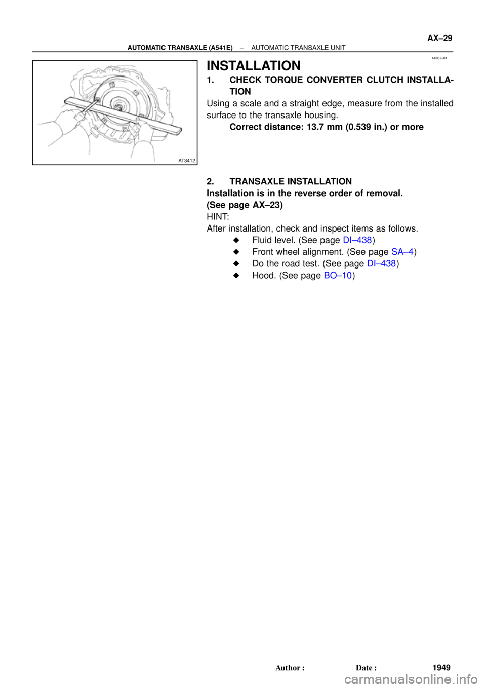
INSTALLATION
1. CHECK TORQUE CONVERTER CLUTCH INSTALLA-
TION
Using a scale and a straight edge, measure from the installed
surface to the transaxle housing.
Correct distance: 13.7 mm (0.539 in.) or more
2. TRANSAXLE INSTALLATION
Installation is in the reverse order of removal.
(See page AX±23)
HINT:
After installation, check and inspect items as follows.
�Fluid level. (See page DI±438)
�Front wheel alignment. (See page SA±4)
�Do the road test. (See page DI±438)
�Hood. (See page BO±10)
Page 1119 of 4592

CL034±01
± CLUTCHTROUBLESHOOTING
CL±1
1780 Author�: Date�:
TROUBLESHOOTING
PROBLEM SYMPTOMS TABLE
Use the table below to help you find the cause of the problem. The numbers indicate the priority of the likely
cause of the problem. Check each part in order. If necessary, replace these parts.
SymptomSuspect AreaSee page
1. Engine mounting (Loosen)±1. Engine mounting (Loosen)
2. Clutch disc (Runout is excessive)
±
CL±17
2. Clutch disc (Runout is excessive)
3. Clutch disc (Oily)
CL±17
CL±17
Clutch grabs/chatters
3. Clutch disc (Oily)
4. Clutch disc (Worn out)
CL±17
CL±17Clutch grabs/chatters4. Clutch disc (Worn out)
5. Clutch disc torsion rubber (Damaged)
CL±17
CL±175. Clutch disc torsion rubber (Damaged)
6. Clutch disc (Glazed)
CL 17
CL±176. Clutch disc (Glazed)
7. Diaphragm spring (Out of tip alignment)
CL 17
CL±19
1. Clutch line (Air in line)±
Clutch pedal spongy
1. Clutch line (Air in line)
2. Master cylinder cup (Damaged)
±
CL±4
Clutch edal s ongy2. Master cylinder cu (Damaged)
3. Release cylinder cup (Damaged)
CL 4
CL±9
1 Release bearing (Worn dirty or damaged)CL 19Clutch noisy1. Release bearing (Worn, dirty, or damaged)
2Cl hdi i bb (D d)
CL±19
CL 17Clutch noisy2. Clutch disc torsion rubber (Damaged)CL±17
1. Clutch pedal (Freeplay out of adjustment)CL±21. Clutch edal (Free lay out of adjustment)
2. Clutch disc (Oily)
CL±2
CL±17
Cl t h li
2. Clutch disc (Oily)
3. Clutch disc (Worn out)
CL±17
CL±17Clutch slips3. Clutch disc (Worn out)
4. Diaphragm spring (Damaged)
CL 17
CL±174. Dia hragm s ring (Damaged)
5. Pressure plate (Distortion)
CL 17
CL±175. Pressure late (Distortion)
6. Flywheel (Distortion)
CL 17
±
1 Clutchpedal (Freeplay out of adjustment)CL±21. Clutch pedal (Freeplay out of adjustment)
2 Clutch line (Air in line)CL±2
2. Clutch line (Air in line)
3 Master cylinder cup(Damaged)
±
CL 43. Master cylinder cup (Damaged)
4 Release cylinder cup(Damaged)
CL±4
CL 94. Release cylinder cup (Damaged)
5 Clutch disc (out of true)
CL±9
CL 175. Clutch disc (out of true)
6 Cl tch disc (R no t is e cessi e)
CL±17
CL 17
Cl t h d t di
6. Clutch disc (Runout is excessive)
7 Cl t h di (Li i b k )
CL±17
CL 17Clutch does not disengage7. Clutch disc (Lining broken)
8 Cl t h di (Di t b d)
CL±17
CL 178. Clutch disc (Dirty or burned)
Cl h di (Oil )
CL±17
CL9. Clutch disc (Oily)CL±17
10. Clutch disc (Lack of spline grease)CL±19
11. Diaphragm spring (Damaged)CL±17gg(g)
12. Diaphragm spring (Out of tip alignment)CL±19gg( g)
13. Pressure plate (Distortion)CL±17
Page 1139 of 4592
CL03M±02
Q10089
1MZ±FE:
5S±FE:SST
Flywheel
Side
SST
Q10084
SST
1
Matchmarks
4
2
6
35
Q10072
SST
± CLUTCHCLUTCH UNIT
CL±21
1800 Author�: Date�:
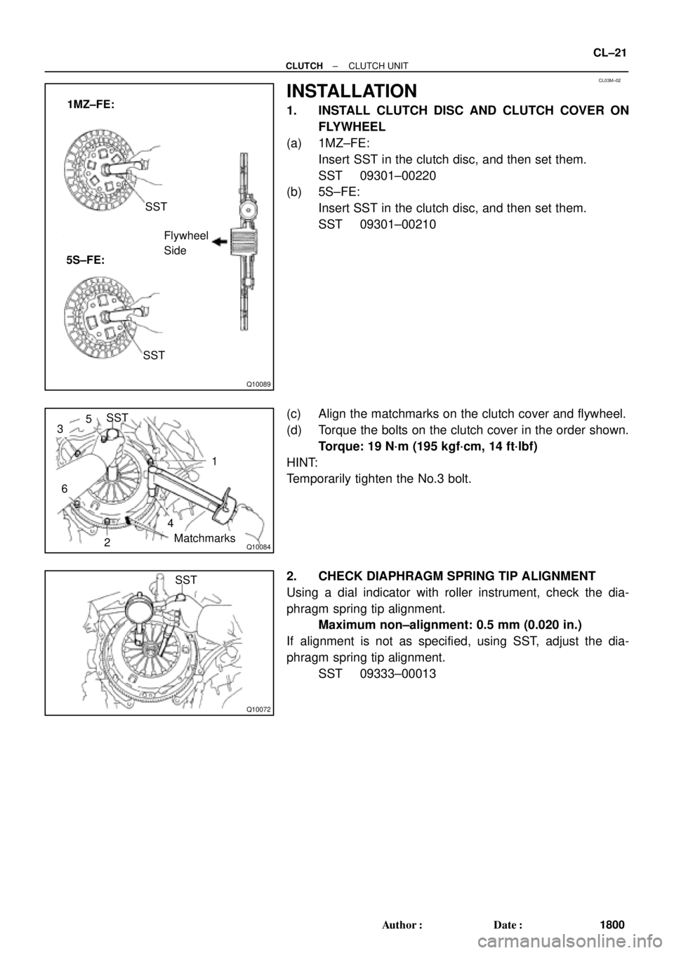
INSTALLATION
1. INSTALL CLUTCH DISC AND CLUTCH COVER ON
FLYWHEEL
(a) 1MZ±FE:
Insert SST in the clutch disc, and then set them.
SST 09301±00220
(b) 5S±FE:
Insert SST in the clutch disc, and then set them.
SST 09301±00210
(c) Align the matchmarks on the clutch cover and flywheel.
(d) Torque the bolts on the clutch cover in the order shown.
Torque: 19 N´m (195 kgf´cm, 14 ft´lbf)
HINT:
Temporarily tighten the No.3 bolt.
2. CHECK DIAPHRAGM SPRING TIP ALIGNMENT
Using a dial indicator with roller instrument, check the dia-
phragm spring tip alignment.
Maximum non±alignment: 0.5 mm (0.020 in.)
If alignment is not as specified, using SST, adjust the dia-
phragm spring tip alignment.
SST 09333±00013
Page 2942 of 4592
MX051±01
± MANUAL TRANSAXLE (E153)MANUAL TRANSAXLE UNIT
MX±9
1810 Author�: Date�:
INSTALLATION
Installation is in the reverse order of removal (See page MX±4).
HINT:
After installation, check and inspect items as follows.
�Front wheel alignment (See page SA±4).
�Do the road test.
Page 2990 of 4592
MX04E±01
MX±8
± MANUAL TRANSAXLE (S51)MANUAL TRANSAXLE UNIT
1858 Author�: Date�:
INSTALLATION
Installation is in the reverse order of removal (See page MX±4).
HINT:
�Front wheel alignment (See page SA±4).
�Do the road test.
Page 3281 of 4592
SS09Q±01
± SERVICE SPECIFICATIONSCLUTCH
SS±43
206 Author�: Date�:
CLUTCH
SERVICE DATA
Pedal height from asphalt sheet 1MZ±FE161.8 ± 171.8 mm (6.370 ± 6.764 in.)
Pedal height from asphalt sheet 5S±FE156.8 ± 166.8 mm (6.173 ± 6.567 in.)
Push rod play at pedal top1.0 ± 5.0 mm (0.039 ± 0.197 in.)
Pedal freeplay5.0 ± 15.0 mm (0.197 ± 0.591 in.)
Clutch start switch ON±OFF Stroke5.0 ± 0.5 mm (0.197 ± 0.020 in.)
Clutch release point from pedal full stroke end position25 mm (0.98 in.) or more
Disc rivet head depth Min.0.3 mm (0.012 in.)
Disc runout Max.0.8 mm (0.031 in.)
Flywheel runoutMax.0.1 mm (0.004 in.)
Diaphragm spring finger wear Max. depth0.6 mm (0.024 in.)
Diaphragm spring finger wear Max. width5.0 mm (0.197 in.)
Diaphragm spring tip non±alignmentMax.0.5 mm (0.020 in.)
Page 3297 of 4592

Cold tire inflationP195/70R1")
SS04W±01
± SERVICE SPECIFICATIONSSUSPENSION AND AXLE
SS±59
222 Author�: Date�:
SUSPENSION AND AXLE
SERVICE DATA
P195/70R14 90SFront, Rear*1210 kPa (2.1 kgf/cm2, 30 psi)
Cold tire inflationP195/70R14 90SFront, Rear*2210 kPa (2.1 kgf/cm2, 30 psi)pressure
(Normal driving)P205/65R15 92HFront, Rear*1220 kPa (2.2 kgf/cm2, 32 psi)(Normal driving)P205/65R15 92HFront, Rear*2200 kPa (2.0 kgf/cm2, 29 psi)
P195/70R14 90SFront, Rear*3210 kPa (2.1 kgf/cm2, 30 psi)
Cold tire inflationP195/70R14 90SFront, Rear*4240 kPa (2.4 kgf/cm2, 35 psi)pressure
(Trailer towing)P205/65R15 92HFront, Rear*3220 kPa (2.2 kgf/cm2, 32 psi)(Trailer towing)P205/65R15 92HFront, Rear*4240 kPa (2.4 kgf/cm2, 35 psi)
V hi l h i ht 195/70R14Front*5212 mm (8.35 in.)Vehicle height195/70R14Rear*6264 mm (10.39 in.)
205/65R15Front*5215 mm (8.46 in.)205/65R15Rear*6266 mm (10.49 in.)
Camber 5S±FE±0°36'±45'(0.6°±0.75°)Camber 5S ± FE
1MZ ± FE
±036 ± 45 (0.6 ± 0.75)
±0°37' ± 45' (0.62° ± 0.75°)1MZ ± FE±037 ± 45 (0.62 ± 0.75)
Left ± right error45' (0.75°) or less
Front wheel
alignment
Caster 5S ± FE
1MZ ± FE
Left ± right error2°10' ± 45' (2.17° ± 0.75°)
2°11' ± 45' (2.18° ± 0.75°)
45' (0.75°) or less
alignmentSteering axis inclination 5S ± FE
1MZ ± FE
Left ± right error13°01' ± 45' (13.02° ± 0.75°)
13°04' ± 45' (13.07° ± 0.75°)
45' (0.75°) or less
Toe±in (Total)
Rack end length difference0° ± 12' (0° ± 0.2°)
0 ± 2 mm (0 ± 0.08 in.)
1.5 mm (0.059 in.) or less
Wh l l 195/70R14Inside wheel 37°12' ± 2° (37.2° ± 2°)Wheel angle195/70R14Outside wheel 32°21' (32.45°)
205/65R15Inside wheel 35°47' ± 2° (35.78° ± 2°)205/65R15Outside wheel 31°25' (31.42°)
Rear wheel
li t
Camber 5S ± FE
1MZ ± FE
Left ± right error±0°42' ± 45' (±0.7° ± 0.75°)
±0°45' ± 45' (±0.75° ± 0.75°)
45' (0.75°) or less
alignmentToe±in (Total)
No.2 lower suspension arm length difference0°24' ± 12' (0.4° ± 0.2°)
4 ± 2 mm (0.16 ± 0.08 in.)
1 mm (0.04 in.) or less
*1: For all loads including rated loads
*2: For reduced loads (1 to 4 passengers)
*3: For driving under 160 km/h (100 mph)
*4: For driving at 160 km/h (100 mph) or over
*5: Front measuring point
Measure from the ground to the center of the front side lower suspension arm mounting bolt.
*6: Rear measuring point
Measure from the ground to the center of the strut rod mounting bolt.