Page 3319 of 4592
Vehicle height
Tire size: 205/65R15Rear*6270 mm (")
SS04W±03
± SERVICE SPECIFICATIONSSUSPENSION AND AXLE
SS±9
67 Author�: Date�:
SUSPENSION AND AXLE
SERVICE DATA
Vehicle heightFront*5218 mm (8.58 in.)Vehicle height
Tire size: 205/65R15Rear*6270 mm (10.63 in.)
Camber0°36'±45'(0 6°±075°)Camber
Ri h l f
±0°36' ± 45' (0.6° ± 0.75°)
45' (0 75°) lRight±left error45' (0.75°) or less
Front wheel
Caster
Right±left error2°10' ± 45' (2.17° ± 0.75°)
45' (0.75°) or less
Front wheel
alignmentSteering axis inclination
Right±left error13°01' ± 45' (13.02° ± 0.75°)
45' (0.75°) or less
Toe±in (Total)
Rack end length difference
0° ± 12' (0° ± 0.2° 0 ± 2 mm 0 ± 0.08 in.)
1.5 mm (0.059 in.) or less
Wheel angle Inside wheel35°50' ± 2° (35.84° ± 2°)Wheel angle Inside wheel
Outside wheel31°28' (31.47°)
Rear wheel
Camber
Right±left error±0°45' ± 45' (±0.75° ± 0.75°)
45' (0.75°) or less
Rear wheel
alignmentToe±in (total)
No. 2 lower suspension arm length difference0°24' ± 12' (0.4° ± 0.2°)
4 ± 2 mm (0.16 ± 0.08 in.)
1 mm (0.04 in.) or less
*1: Front measuring point
Measure the distance from the ground to the center of the front side lower suspension arm mounting bolt.
*
2: Rear measuring point
Measure the distance from the ground to the center of the front side strut rod mounting bolt.
FtlAxle bearing backlash Maximum0.05 mm (0.0020 in.)Front axleAxle hub deviationMaximum0.05 mm (0.0020 in.)
Front drive shaft
Drive shaft standard length
LH
RH
609.2 ± 2.0 mm (23.984 ± 0.079 in.)
842.9 ± 2.0 mm (33.185 ± 0.079 in.)
Ft iLower ball joint turning torque1.0 ± 3.4 N´m (10 ± 35 kgf´cm, 8.7 ± 30 in.´lbf)Front suspensionStabilizer bar link turning torque0.05 ± 1.0 N´m (0.5 ± 10 kgf´cm, 0.4 ± 8.7 in.´lbf)
RlAxle bearing backlash0.05 mm (0.0020 in.)Rear axleAxle hub deviation0.07 mm (0.0028 in.)
RiNo. 2 lower suspension arm length512.3 mm (20.169 in.)Rear suspensionStabilizer bar link turning torque0.05 ± 1.0 N´m (0.5 ± 10 kgf´cm, 0.4 ± 8.7 in.´lbf)
Page 3508 of 4592

SR06C±01
SR±2
± STEERINGTROUBLESHOOTING
2097 Author�: Date�:
TROUBLESHOOTING
PROBLEM SYMPTOMS TABLE
Use the table below to help you find the cause of the problem. The numbers indicate the priority of the likely
cause of the problem. Check each part in the order shown. If necessary, repair or replace these parts.
SymptomSuspect AreaSee page
Hard steering
1. Tires (Improperly inflated)
2. Power steering fluid level (Low)
3. Drive belt (Loose)
4. Front wheel alignment (Incorrect)
5. Steering system joints (Worn)
6. Suspension arm ball joints (Worn)
7. Steering column (Binding)
8. Power steering vane pump
9. Power steering gearSA±2
SR±5
SR±3
SA±4
±
SA±45
±
SR±18
SR±31
Poor return
1. Tires (Improperly inflated)
2. Front wheel alignment (Incorrect)
3. Steering column (Binding)
4. Power steering gearSA±2
SA±4
±
SR±31
Excessive play
1. Steering system joints (Worn)
2. Suspension arm ball joints (Worn)
3. Intermediate shaft, Sliding yoke (Worn)
4. Front wheel bearing (Worn)
5. Power steering gear±
SA±45
±
SA±10
SR±31
Abnormal noise
1. Power steering fluid level (Low)
2. Steering system joints (Worn)
3. Power steering vane pump
4. Power steering gearSR±5
±
SR±18
SR±31
Page 3556 of 4592
SR±50
± STEERINGPOWER STEERING GEAR
2145 Author�: Date�:
13. TORQUE STEERING WHEEL SET NUT
Torque: 35 N´m (360 kgf´cm, 26 ft´lbf)
14. INSTALL STEERING WHEEL PAD
(See page SR±16)
15. CHECK FRONT WHEEL ALIGNMENT
(See page SA±4)
Page 3557 of 4592

SA077±01
± SUSPENSION AND AXLETROUBLESHOOTING
SA±1
1952 Author�: Date�:
TROUBLESHOOTING
PROBLEM SYMPTOMS TABLE
Use the table below to help you find the cause of the problem. The numbers indicate the priority of the likely
cause of the problem. Check each part in order. If necessary, replace these parts.
SymptomSuspect AreaSee page
Wander/pulls
1. Tire (Worn or improperly inflated)
2. Wheel alignment (Incorrect)
3. Steering linkage (Loosen or worn)
4. Hub bearings (Worn)
5. Suspension parts (Worn)
6. Steering gear (Out of adjustment or broken)SA±2
SA±4
SA±7
±
SA±10
±
±
Bottoming
1. Vehicle (Overloaded)
2. Spring (Weak)
3. Shock absorber (Worn)±
SA±33
SA±56
SA±33
SA±56
Sways/pitches
1. Tire (Worn or improperly inflated)
2. Stabilizer bar (Bent or broken)
3. Shock absorber (Worn)SA±2
SA±47
SA±69
SA±33
SA±56
Front wheel shimmy
1. Tire (Worn or improperly inflated)
2. Wheels (Out of balance)
3. Shock absorber (Worn)
4. Wheel alignment (Incorrect)
5. Ball joints (Worn)
6. Hub bearings (Worn)
7. Steering linkage (Loosen or worn)
8. Steering gear (Out of adjustment or broken)SA±2
SA±2
SA±33
SA±56
SA±4
SA±7
SA±43
SA±10
±
±
Abnormal tire wear
1. Tire (Worn or improperly inflated)
2. Wheels (Out of balance)
3. Suspension parts (Worn)
4. Shock absorber (Worn)SA±2
SA±2
±
SA±33
SA±56
Page 3560 of 4592

W03085
Front
R03030
Rear
SA079±01
Z03382
SA3213
AB
C D
Front SA±4
± SUSPENSION AND AXLEFRONT WHEEL ALIGNMENT
1955 Author�: Date�:
FRONT WHEEL ALIGNMENT
INSPECTION
1. MEASURE VEHICLE HEIGHT
Tire sizeFront*1 mm (in.)Rear*2 mm (in.)
195/70R14212 (8.35)264 (10.39)
205/65R15215 (8.46)266 (10.49)
*1: Front measuring point
Measure from the ground to the center of the front side lower
suspension arm mounting bolt.
*
2: Rear measuring point
Measure from the ground to the center of the strut rod mounting
bolt.
NOTICE:
Before inspecting the wheel alignment, adjust the vehicle
height to the specification.
If the vehicle height is not within the specification, try to adjust
it by pushing down on or lifting the body.
2. INSTALL CAMBER±CASTER±KINGPIN GAUGE
ONTO VEHICLE OR POSITION VEHICLE ON WHEEL
ALIGNMENT TESTER
Follow the specific instructions of the equipment manufacturer.
3. INSPECT CAMBER, CASTER AND STEERING AXIS
INCLINATION
5S±FE1MZ±FE
Camber
Left±right error±0°36' ± 45'
(±0.6° ± 0.75°)
45' (0.75°) or less±0°37' ± 45'
(±0.62° ± 0.75°)
45' (0.75°) or less
Caster
Left±right error2°10' ± 45'
(2.17° ± 0.75°)
45' (0.75°) or less2°11' ± 45'
(2.18° ± 0.75°)
45' (0.75°) or less
Steering axis inclination
Left±right error13°01' ± 45'
(13.02° ± 0.75°)
45' (0.75°) or less13°04' ± 45'
(13.07° ± 0.75°)
45' (0.75°) or less
HINT:
If the caster and steering axis inclination are not within the spec-
ification, after the camber has correctly adjusted, recheck the
suspension parts for damaged and/or worn out parts.
4. INSPECT TOE±IN
Toe±in
(Total)A + B: 0° ± 12' (0° ± 0.2°)
C ± D: 0 ± 2 mm (0 ± 0.08 in.)
If the toe±in is not within the specification, adjust it at the rack
ends.
Page 3561 of 4592

W03086
F02267
1
2
F01195
Bolt
Adjusting
ValueSet Bolt
15'
30'Adjusting Bolt90105±15001 90105±15004 90105±15005 90105±15006
45'
1°00'
1°15'
1°30'121212121 Dot 2 Dots 3 Dots
± SUSPENSION AND AXLEFRONT WHEEL ALIGNMENT
SA±5
1956 Author�: Date�:
5. ADJUST CAMBER
NOTICE:
After the camber has been adjusted, inspect the toe±in.
(a) Remove the front wheels and speed sensor clamp.
(b) Remove the 2 nuts on the lower side of the shock absorb-
er.
(c) Coat the threads of the nuts with engine oil.
(d) Temporarily install the 2 nuts.
(e) Adjust the camber by pushing or pulling the lower side of
the shock absorber in the direction in which the camber
adjustment is required.
(f) Tighten the nuts.
Torque: 211 N´m (2,150 kgf´cm, 156 ft´lbf)
(g) Install the front wheels.
Torque: 103 N´m (1,050 kgf´cm, 76 ft´lbf)
(h) Check the camber.
HINT:
�Try to adjust the camber to the center value.
�Adjusting value for the set bolts is 6' ± 30' (0.1° ± 0.5°).
If the camber is not within the specification, using the table be-
low, estimate for how much additional camber adjustment will
be required, and select the camber adjusting bolt.
(i) Follow the above mentioned steps again. Between step
(b) and (c), exchange 1 or 2 selected bolts.
HINT:
When exchanging the 2 bolts, exchange 1 bolt for each time.
Page 3562 of 4592
W03088
SA0028
A: Inside
B: Outside AB
Front BA SA±6
± SUSPENSION AND AXLEFRONT WHEEL ALIGNMENT
1957 Author�: Date�:
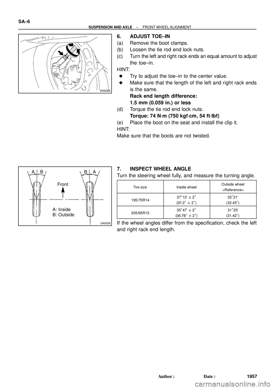
6. ADJUST TOE±IN
(a) Remove the boot clamps.
(b) Loosen the tie rod end lock nuts.
(c) Turn the left and right rack ends an equal amount to adjust
the toe±in.
HINT:
�Try to adjust the toe±in to the center value.
�Make sure that the length of the left and right rack ends
is the same.
Rack end length difference:
1.5 mm (0.059 in.) or less
(d) Torque the tie rod end lock nuts.
Torque: 74 N´m (750 kgf´cm, 54 ft´lbf)
(e) Place the boot on the seat and install the clip it.
HINT:
Make sure that the boots are not twisted.
7. INSPECT WHEEL ANGLE
Turn the steering wheel fully, and measure the turning angle.
Tire sizeInside wheelOutside wheel
195/70R1437°12' ± 2°
(37.2° ± 2°)32°21'
(32.45°)
205/65R1535°47' ± 2°
(35.78° ± 2°)31°25'
(31.42°)
If the wheel angles differ from the specification, check the left
and right rack end length.
Page 3563 of 4592

SA07A±01
SA3213
AB
C D
Front
W03090
± SUSPENSION AND AXLEREAR WHEEL ALIGNMENT
SA±7
1958 Author�: Date�:
REAR WHEEL ALIGNMENT
INSPECTION
1. MEASURE VEHICLE HEIGHT
Vehicle height: See page SA±4
NOTICE:
Before inspecting the wheel alignment, adjust the vehicle
height to specification.
2. INSTALL CAMBER ± CASTER ± KINGPIN GAUGE
ONTO VEHICLE OR POSITION VEHICLE ON WHEEL
ALIGNMENT TESTER
Follow the specific instructions on the equipment manufacturer.
3. INSPECT CAMBER
5S±FE1MZ±FE
Camber
Left±right error±0°42' ± 45'
(±0.7° ± 0.75°)
45' (0.75°) or less±0°45' ± 45'
(±0.75° ± 0.75°)
45' (0.75°) or less
HINT:
Camber in not adjustable, it measurement is not within the
specifications, inspect the suspension parts for damaged and/
or worn±out parts and replace them as necessary.
4. INSPECT TOE±IN
Toe±in
(Total)A + B: 0°24' ± 12' (0.4° ± 0.2°)
C ± D: 4 ± 2 mm (0.16 ± 0.08 in.)
If the toe±in is not within the specification, adjust it at the No.2
lower suspension arm.
5. ADJUST TOE±IN
(a) Measure the length of the left and right No.2 lower sus-
pension arms.
No.2 lower suspension arm length difference:
1 mm (0.04 in.) or less
If the left±right difference is larger than the specification, adjust
the length.