Page 105 of 4592
Q00394
SST
AX03B±01
Q00247
SST
± AUTOMATIC TRANSAXLE (A140E)DIFFERENTIAL OIL SEAL
AX±11
1904 Author�: Date�:
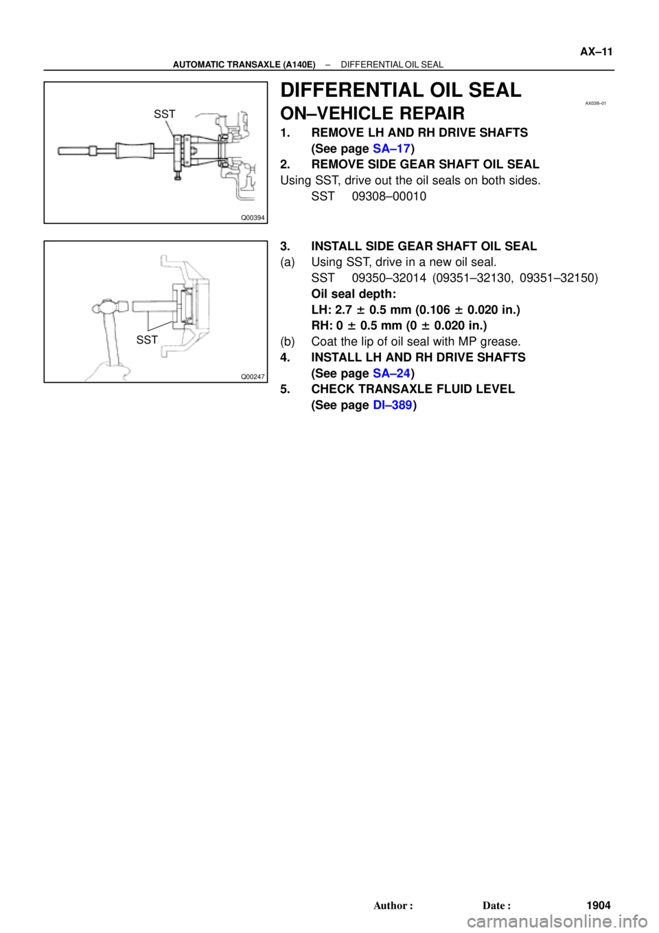
DIFFERENTIAL OIL SEAL
ON±VEHICLE REPAIR
1. REMOVE LH AND RH DRIVE SHAFTS
(See page SA±17)
2. REMOVE SIDE GEAR SHAFT OIL SEAL
Using SST, drive out the oil seals on both sides.
SST 09308±00010
3. INSTALL SIDE GEAR SHAFT OIL SEAL
(a) Using SST, drive in a new oil seal.
SST 09350±32014 (09351±32130, 09351±32150)
Oil seal depth:
LH: 2.7 ± 0.5 mm (0.106 ± 0.020 in.)
RH: 0 ± 0.5 mm (0 ± 0.020 in.)
(b) Coat the lip of oil seal with MP grease.
4. INSTALL LH AND RH DRIVE SHAFTS
(See page SA±24)
5. CHECK TRANSAXLE FLUID LEVEL
(See page DI±389)
Page 114 of 4592
AUTOMATIC TRANSAXLE UNIT
1913 Author�: Date�:
14. REMOVE EXHAUST MANIFOLD STAY
Remove the 2 bolts and exhaust manifold stay.
Torque: 42 N´m (")
Q10058
Q10059
Q00251
AX±20
± AUTOMATIC TRANSAXLE (A140E)AUTOMATIC TRANSAXLE UNIT
1913 Author�: Date�:
14. REMOVE EXHAUST MANIFOLD STAY
Remove the 2 bolts and exhaust manifold stay.
Torque: 42 N´m (430 kgf´cm, 31 ft´lbf)
15. REMOVE TRANSAXLE±TO±ENGINE BOLT
Torque: 66 N´m (670 kgf´cm, 48 ft´lbf)
16. REMOVE ENGINE HOOD
(a) Disconnect the washer pipe.
(b) Remove the 4 bolts and engine hood.
Torque: 14 N´m (145 kgf´cm, 10 ft´lbf)
17. RAISE AND SUPPORT VEHICLE SECURELY
18. REMOVE FRONT WHEELS
Torque: 103 N´m (1,050 kgf´cm, 76 ft´lbf)
19. REMOVE ENGINE UNDER COVER AND CENTER EN-
GINE UNDER COVER
20. DISCONNECT SHIFT CONTROL CABLE
(a) Remove the nut and disconnect the shift control cable
from the park/neutral position switch.
Torque: 15 N´m (150 kgf´cm, 11 ft´lbf)
(b) Remove the clip and disconnect the shift control cable
from the bracket.
21. REMOVE DIFFERENTIAL FLUID DRAIN PLUG AND
GASKET
HINT:
At the time of installation, please refer to the following item.
Replace the used gasket with a new gasket.
22. DRAIN DIFFERENTIAL FLUID
23. REMOVE LH AND RH FENDER APRON SEALS
24. REMOVE LH AND RH DRIVE SHAFTS
(See page SA±17)
Page 136 of 4592
Q00394
SST
AX03S±01
Q06348
SST
Q00238
SST
± AUTOMATIC TRANSAXLE (A541E)DIFFERENTIAL OIL SEAL
AX±15
1935 Author�: Date�:
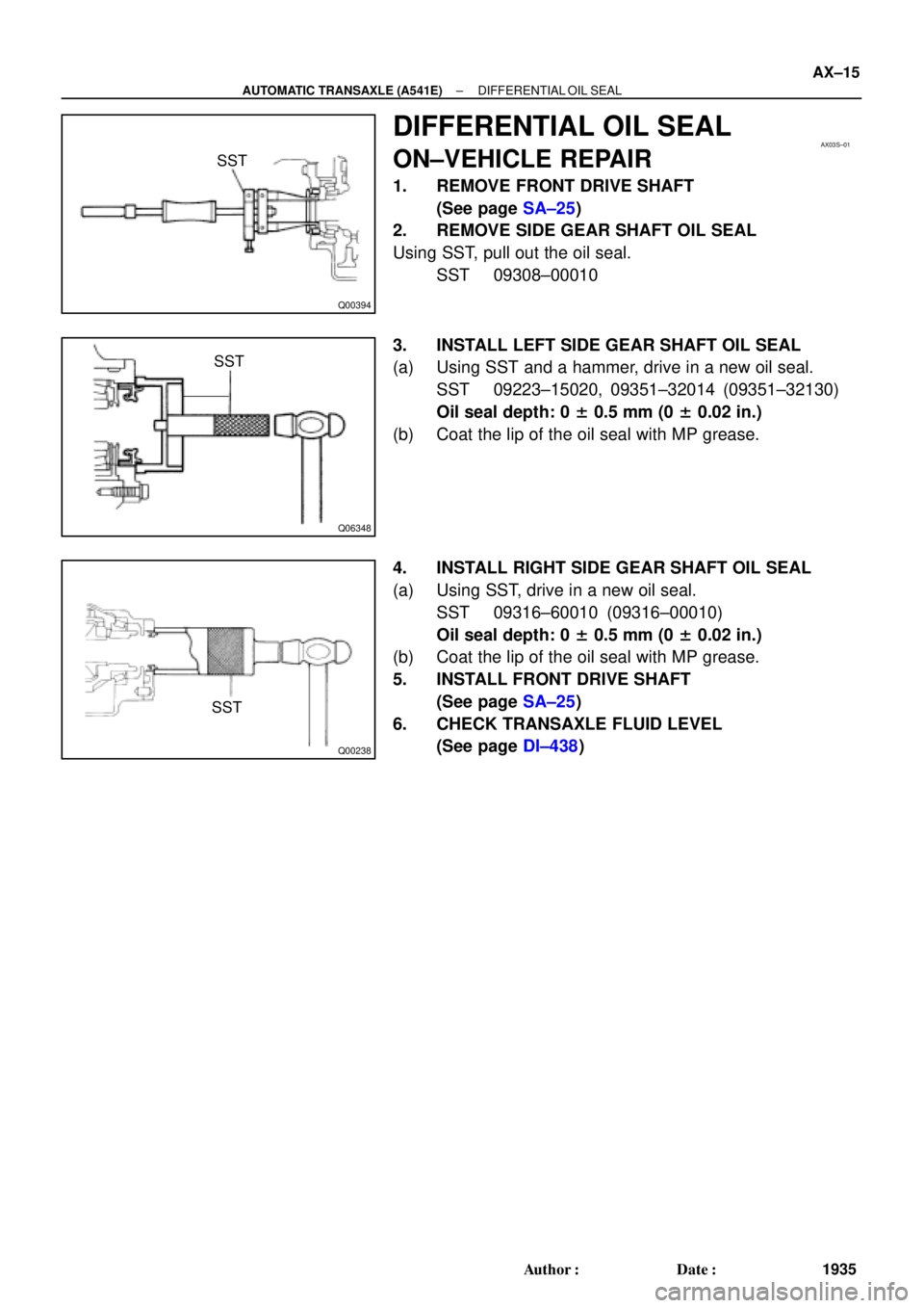
DIFFERENTIAL OIL SEAL
ON±VEHICLE REPAIR
1. REMOVE FRONT DRIVE SHAFT
(See page SA±25)
2. REMOVE SIDE GEAR SHAFT OIL SEAL
Using SST, pull out the oil seal.
SST 09308±00010
3. INSTALL LEFT SIDE GEAR SHAFT OIL SEAL
(a) Using SST and a hammer, drive in a new oil seal.
SST 09223±15020, 09351±32014 (09351±32130)
Oil seal depth: 0 ± 0.5 mm (0 ± 0.02 in.)
(b) Coat the lip of the oil seal with MP grease.
4. INSTALL RIGHT SIDE GEAR SHAFT OIL SEAL
(a) Using SST, drive in a new oil seal.
SST 09316±60010 (09316±00010)
Oil seal depth: 0 ± 0.5 mm (0 ± 0.02 in.)
(b) Coat the lip of the oil seal with MP grease.
5. INSTALL FRONT DRIVE SHAFT
(See page SA±25)
6. CHECK TRANSAXLE FLUID LEVEL
(See page DI±438)
Page 145 of 4592
AUTOMATIC TRANSAXLE UNIT
1944 Author�: Date�:
12. REMOVE 2 FRONT SIDE ENGINE MOUNTING BOLTS
Torque:
TMC Made: 80 N´m (820 kgf´cm, 59")
Q06478
Q10286
Q06530
Q10038
AX±24
± AUTOMATIC TRANSAXLE (A541E)AUTOMATIC TRANSAXLE UNIT
1944 Author�: Date�:
12. REMOVE 2 FRONT SIDE ENGINE MOUNTING BOLTS
Torque:
TMC Made: 80 N´m (820 kgf´cm, 59 ft´lbf)
TMMK Made:
Green color bolt: 66 N´m (670 kgf´cm, 48 ft´lbf)
Silver color bolt: 44 N´m (440 kgf´cm, 32 ft´lbf)
13. REMOVE STARTER AND A/T SHIFT CABLE CLAMP
(a) Disconnect the connector and remove the nut.
(b) Remove the 2 bolts, starter and A/T shift cable clamp.
Torque: 39 N´m (400 kgf´cm, 29 ft´lbf)
14. REMOVE EXHAUST MANIFOLD BRACKET MOUNT-
ING BOLT
Torque:
Except California: 20 N´m (200 kgf´cm, 15 ft´lbf)
California: 34 N´m (350 kgf´cm, 25 ft´lbf)
15. REMOVE 5 TRANSAXLE±TO±ENGINE BOLTS AND
DISCONNECT GROUND TERMINAL
Torque: 66 N´m (670 kgf´cm, 48 ft´lbf)
16. REMOVE ENGINE HOOD
(a) Disconnect the washer pipe.
(b) Remove the 4 bolts and engine hood.
Torque: 26 N´m (265 kgf´cm, 19 ft´lbf)
17. RAISE AND SUPPORT VEHICLE SECURELY
18. REMOVE FRONT WHEELS
Torque: 103 N´m (1,050 kgf´cm, 76 ft´lbf)
19. REMOVE DIFFERENTIAL FLUID DRAIN PLUG AND
GASKET
HINT:
At the time of installation, please refer to the following item.
Replace the used gasket with a new gasket.
20. DRAIN DIFFERENTIAL FLUID
21. REMOVE LH AND RH ENGINE SIDE COVERS
22. REMOVE LH AND RH FRONT DRIVE SHAFTS
(See page SA±25)
Page 159 of 4592

IATIntake Air TemperatureIntake or Inlet Air Temperature
ICMIgnition Control Module±
IFIIndirect Fuel")
INTRODUCTIONGLOSSARY OF SAE AND TOYOTA TERMS ±
IN±7
IACIdle Air ControlIdle Speed Control (ISC)
IATIntake Air TemperatureIntake or Inlet Air Temperature
ICMIgnition Control Module±
IFIIndirect Fuel InjectionIndirect Injection
IFSInertia Fuel±Shutoff±
ISCIdle Speed Control±
KSKnock SensorKnock Sensor
MAFMass Air FlowAir Flow Meter
MAPManifold Absolute PressureManifold Pressure
Intake Vacuum
MCMixture Control
Electric Bleed Air Control Valve (EBCV)
Mixture Control Valve (MCV)
Electric Air Control Valve (EACV)
MDPManifold Differential Pressure±
MFIMultiport Fuel InjectionElectronic Fuel Injection (EFI)
MILMalfunction Indicator LampCheck Engine Light
MSTManifold Surface Temperature±
MVZManifold Vacuum Zone±
NVRAMNon±Volatile Random Access Memory±
O2SOxygen SensorOxygen Sensor, O2 Sensor (O2S)
OBDOn±Board DiagnosticOn±Board Diagnostic (OBD)
OCOxidation Catalytic ConverterOxidation Catalyst Converter (OC), CCo
OPOpen LoopOpen Loop
PAIRPulsed Secondary Air InjectionAir Suction (AS)
PCMPowertrain Control Module±
PNPPark/Neutral Position±
PROMProgrammable Read Only Memory±
PSPPower Steering Pressure±
PTOXPeriodic Trap OxidizerDiesel Particulate Filter (DPF)
Diesel Particulate Trap (DPT)
RAMRandom Access MemoryRandom Access Memory (RAM)
RMRelay Module±
ROMRead Only MemoryRead Only Memory (ROM)
RPMEngine SpeedEngine Speed
SCSuperchargerSupercharger
SCBSupercharger Bypass±
SFISequential Multiport Fuel InjectionElectronic Fuel Injection (EFI), Sequential Injection
SPLSmoke Puff Limiter±
SRIService Reminder Indicator±
SRTSystem Readiness Test±
STScan Tool±
TBThrottle BodyThrottle Body
TBIThrottle Body Fuel InjectionSingle Point Injection
Central Fuel Injection (Ci)
TCTurbochargerTurbocharger
TCCTorque Converter ClutchTorque Converter
TCMTransmission Control ModuleTransmission ECU (Electronic Control Unit)
TPThrottle PositionThrottle Position
TRTransmission Range±
Page 168 of 4592
AUTOMATIC TRANSAXLESERVICE SPECIFICATIONS ±
AX±16
Differential
Drive pinion preload (at starting) New bearing
Reused bearing
1.0 ± 1.6 N´m
10 ± 16 kgf´cm 8.7 ± 13.9 in.´lbf
0.5 ± 0.8 N´m
5 ± 8 kgf´cm 4.3 ± 6.9 in.´lbf
Total preload (at starting)
New bearing
Reused bearing
Add drive pinion preload
0.3 ± 0.4 N´m
2.9 ± 4.0 kgf´cm 2.5 ± 3.5 in.´lbf
0.1 ± 0.2 N´m
1.5 ± 2.0 kgf´cm 1.3 ± 1.7 in.´lbf
Pinion to side gear backlash0.05 ± 0.20 mm
0.0020 ± 0.0079 in.
Side gear thrust washer thickness
0.95 mm
0.0374 in.
1.00 mm
0.0394 in.
1.05 mm
0.0413 in.
1.10 mm
0.0433 in.
1.20 mm
0.0427 in.
Page 170 of 4592
AUTOMATIC TRANSAXLESERVICE SPECIFICATIONS ±
AX±18
TORQUE SPECIFICATION
Part tightenedN´mkgf´cmft´lbf
Stator shaft x Oil pump body101007
Upper valve body x Lower valve body5.45548
Ring gear x Differential case9798571
Side bearing cap x Transaxle case7273053
Bearing retainer x Transaxle case1919514
Counter drive gear x Drive pinion1721,750127
Carrier cover x Transaxle case2525018
Parking lock pawl bracket7.47565 in.´lbf
Overdrive case x Transaxle case2526019
Oil pump x Transaxle case2222016
Valve body x Transaxle case101007
Manual valve body x Transaxle case101007
Detent spring x Valve body101007
Oil tube bracket x Transaxle case101007
Oil strainer x Valve body101007
Oil pan x Transaxle case4.95043 in.´lbf
Park/Neutral position switch6.97061 in.´lbf
Park/Neutral position switch adjusting bolt5.45548 in.´lbf
Union2727520
AT06Q±0C
Page 172 of 4592
AUTOMATIC TRANSAXLEGENERAL DESCRIPTION ±
AX±2
General Specifications
Type of TransaxleA140E
Type of Engine5S±FE
Torque Converter Clutch Stall Torque Ratio2.0 : 1
Lock±up MechanismEquipped
Gear Ratio 1st Gear
2nd Gear
3rd Gear
O/D Gear
Reverse Gear2.810
1.549
1.000
0.706
2.296
Number of Discs and Plates O/D Direct Clutch (C0)
Forward Clutch (C
1)
Direct Clutch (C
2)
Second Brake (B
2)
First and Reverse Brake (B
3)
O/D Brake (B
0)
2/1
4/4
3/3
3/3
6/5
2/3
B1 Band Width mm (in.)25 mm (0.98 in.)
ATF TypeATF DEXRON ® @@@@@: [g 2]
Capacity liter (US qts, Imp. qts)
Transaxle
Differential
5.6 (5.9, 4.9)
1.6 (1.7, 1.4)
 New bearing
Reused bearing
1.0 ± 1.6 N´m
10 ± 16 kgf´cm 8.7 ± 13.9 in.´lbf
0.5 ± 0.8 N´m
5 �")

