Page 3290 of 4592

SS09N±01
SS±52
± SERVICE SPECIFICATIONSMANUAL TRANSAXLE (S51)
215 Author�: Date�:
TORQUE SPECIFICATION
Part tightenedN´mkgf´cmft´lbf
Transaxle x Engine 17 mm head6465047Transaxle x Engine 17 mm head
14 mm head
64
46
650
470
47
34
Cruise control actuator x Body (w/ Cruise control)131309
Starter x Transaxle3737828
Clutch release cylinder x Transaxle121209
Clutch line bracket x Transaxle Bolt A121209Clutch line bracket x Transaxle Bolt A
(See page MX±4) Bolt B
12
6.9
120
70
9
61 in.´lbf
Manifold stay Front side4242531
Manifold stay Rear side3940029
Front wheel1031,05076
Exhaust pipe bracket Bolt1919514Exhaust ie bracket Bolt
Nut
19
33
195
330
14
24
Front exhaust pipe x Exhaust manifold6263046
Front exhaust pipe x Center exhaust pipe5657041
No.1 exhaust pipe support bracket x Front suspension member3333024
Stabilizer bar link x Stabilizer bar3940029
Stabilizer bar bracket x Front suspension member1919514
PS gear assembly x Front suspension member1811,850134
Front engine mounting insulator x Front suspension member Silver bolt4445033Front engine mounting insulator x Front sus ension member Silver bolt
Green bolt
44
66
450
670
33
48
LH engine mounting insulator x Front suspension member8082059
LH engine mounting bracket x Transaxle6465047
Rear engine mounting insulator x Front suspension member6667048
Steering return pipe x Front suspension member101007
Front suspension member with lower suspension arm Bolt A1811,850134Front sus ension member with lower sus ension arm Bolt A
Bolt B
181
32
1,850
330
134
24Bolt B
(See page MX±4) Nut C
32
36
330
370
24
27
LH stiffener plate3738027
RH stiffener plate3940029
Rear end plate9.39582 in.´lbf
Shift cable grommet retainer x Body4.95043 in.´lbf
Shift lever assembly x Body121209
Transmission case x Transaxle case2930022
Transmission case x Case cover2930022
Transmission case protector1818513
Rear bearing retainer4243031
Output shaft front bearing lock plate1818513
Transaxle case receiver set bolt7.47565 in.´lbf
5th driven gear lock nut1231,25090
Reverse idler shaft lock bolt2930022
Control shaft cover3737527
Control shift lever x Lever shaft6.46556 in.´lbf
Ring gear x Differential case8385061
Selecting bellcrank x Transmission case3738027
Page 3291 of 4592
± SERVICE SPECIFICATIONSMANUAL TRANSAXLE (S51)
SS±53
216 Author�: Date�:
Engine mount bracket x Transaxle5253038
Reverse shift arm bracket1818513
No.3 shift fork x Shift fork shaft1818513
Lock ball assembly2930022
Filler and Drain plugs4950036
Back±up light switch4445033
Differential side bearing retainer1818513
Release bearing retainer7.47565 in.´lbf
Straight screw plug131309
Vehicle speed sensor driven gear5.45548 in.´lbf
Clutch release fork support3940029
Page 3292 of 4592

SS0AS±01
SS±54
± SERVICE SPECIFICATIONSAUTOMATIC TRANSAXLE (A140E)
217 Author�: Date�:
AUTOMATIC TRANSAXLE (A140E)
SERVICE DATA
Line pressure (Wheel locked)
Engine idling
D position
R position
at stall (Throttle valve fully opened)
D position
R position
363 ± 422 kPa (3.7 ± 4.3 kgf/cm2, 53 ± 61 psi)
618 ± 794 kPa (6.3 ± 8.1 kgf/cm2, 90 ± 115 psi)
735 ± 862 kPa (7.5 ± 8.8 kgf/cm
2, 107 ± 125 psi)
1,373 ± 1,608 kPa (14.0 ± 16.4 kgf/cm2, 199 ± 233 psi)
Engine stall revolution D and R positions2,450 ± 150 rpm
Time lag N " D position
N " R positionLess than 1.2 seconds
Less than 1.5 seconds
Engine idle speed A/C OFF and N range750 ± 50 rpm
Throttle cable adjustment
(Throttle valve fully opened)Between boot end face and inner cable stopper
0 ± 1 mm (0 ± 0.04 in.)
Drive plate runoutMax.
Torque converter runout Max.
Torque converter installation distance0.20 mm (0.0079 in.)
0.30 mm (0.0118 in.)
More than 13.0 mm (0.512 in.)
Differential oil seal drive in depth LH side
RH side2.7 ± 0.5 mm (0.106 ± 0.020 in.)
0 ± 0.5 mm (0 ± 0.020 in.)
Shift point
D position
(Throttle valve fully opened) 1 " 2
2 " 3
3 " O/D
O/D " 3
3 " 2
2 " 1
(Throttle valve fully closed) O/D " 3
3 " O/D
2 position
(Throttle valve fully opened) 1 " 2
3 " 2
2 " 1
L position
(Throttle valve fully opened) 2 "1
*1: The maximum vehicle speed for manual shift down when shifting down
from D to 2.
*2: The maximum vehicle speed for manual shift down when shifting down
from 2 to L.
58 ± 63 km/h (36 ± 39 mph)
109 ± 117 km/h (68 ± 73 mph)
145 ± 151 km/h (90 ± 94 mph)
138 ± 146 km/h (86 ± 91 mph)
100 ± 108 km/h (62 ± 67 mph)
51 ± 56 km/h (32 ± 35 mph)
38 ± 43 km/h (24 ± 27 mph)
18 ± 22 km/h (11 ± 14 mph)
58 ± 63 km/h (36 ± 39 mph)
106 ± 114 km/h (66 ± 71 mph)
51 ± 56 km/h (32 ± 35 mph)
47 ± 51 km/h (29 ± 32 mph)
Lock±up point (Throttle valve fully opened)
D position
3rd Gear (O/D main switch OFF)
Lock±up ON
Lock±up OFF
O/D gear
Lock±up ON
Lock±up OFF
67 ± 72 km/h (42 ± 45 mph)
64 ± 69 km/h (40 ± 43 mph)
67 ± 72 km/h (42 ± 45 mph)
64 ± 69 km/h (40 ± 43 mph)
Page 3574 of 4592

W03143
LH
W03144
RH SA±18
± SUSPENSION AND AXLEFRONT DRIVE SHAFT (5S±FE)
1969 Author�: Date�:
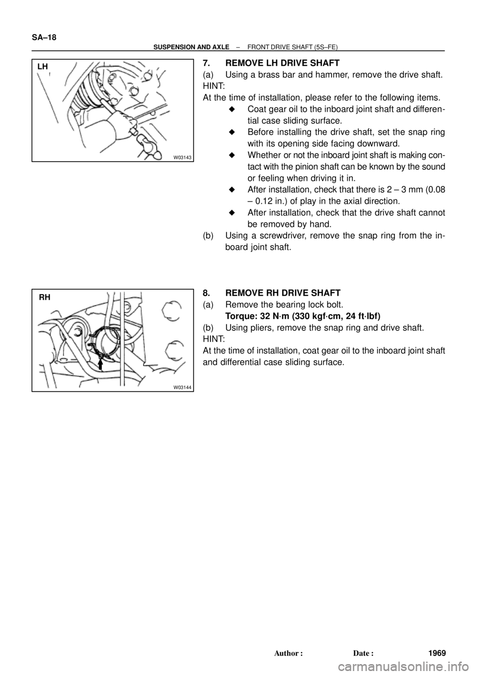
7. REMOVE LH DRIVE SHAFT
(a) Using a brass bar and hammer, remove the drive shaft.
HINT:
At the time of installation, please refer to the following items.
�Coat gear oil to the inboard joint shaft and differen-
tial case sliding surface.
�Before installing the drive shaft, set the snap ring
with its opening side facing downward.
�Whether or not the inboard joint shaft is making con-
tact with the pinion shaft can be known by the sound
or feeling when driving it in.
�After installation, check that there is 2 ± 3 mm (0.08
± 0.12 in.) of play in the axial direction.
�After installation, check that the drive shaft cannot
be removed by hand.
(b) Using a screwdriver, remove the snap ring from the in-
board joint shaft.
8. REMOVE RH DRIVE SHAFT
(a) Remove the bearing lock bolt.
Torque: 32 N´m (330 kgf´cm, 24 ft´lbf)
(b) Using pliers, remove the snap ring and drive shaft.
HINT:
At the time of installation, coat gear oil to the inboard joint shaft
and differential case sliding surface.
Page 3642 of 4592

SA1EC±02
SA±14
± SUSPENSION AND AXLEFRONT DRIVE SHAFT
INSTALLATION
1. LH drive shaft:
INSTALL DRIVE SHAFT TO TRANSAXLE
(a) Install a new snap ring to the inboard joint shaft.
(b) Coat the gear oil to the inboard joint shaft and differential case sliding surface.
(c) Set the snap ring with opening side facing downward.
(d) Using a brass bar and hammer, install the drive shaft.
NOTICE:
Be careful not to damage the dust cover of the drive shaft and oil seal lip of the transaxle.
HINT:
Whether the inboard joint shaft is in contact with the pinion shaft or not can be known from the sound or feel-
ing when driving it in.
(e) Check that there is 2 ± 3 mm (0.08 ± 0.12 in.) of play in the axial direction.
(f) Check that the drive shaft cannot be removed by hand.
2. RH drive shaft:
INSTALL DRIVE SHAFT TO TRANSAXLE
(a) Install the drive shaft.
NOTICE:
Be careful not to damage the dust cover of the drive shaft and oil seal lip of the transaxle.
(b) Using pliers, install a new snap ring.
(c) Install a new bearing lock bolt.
Torque: 32 N´m (330 kgf´cm, 24 ft´lbf)
3. CONNECT DRIVE SHAFT TO AXLE HUB
NOTICE:
Be careful not to damage the boot and ABS speed sensor rotor.
4. CONNECT LOWER SUSPENSION ARM TO LOWER BALL JOINT
Torque: 127 N´m (1,300 kgf´cm, 94 ft´lbf)
5. CONNECT TIE ROD END TO STEERING KNUCKLE
(a) Connect the tie rod end to the steering knuckle.
(b) Install the nut and a new cotter pin.
If the holes for the cotter pin are not aligned, tighten the nut further up to 60°.
Torque: 49 N´m (500 kgf´cm, 36 ft´lbf)
6. INSTALL DRIVE SHAFT LOCK NUT
(a) While applying brakes, install the nut.
Torque: 294 N´m (3,000 kgf´cm, 217 ft´lbf)
(b) Install the lock cap and a new cotter pin.
If the holes for the cotter pin are not aligned, tighten the nut further up to 60°.
7. FILL AND CHECK ATF (See page DI±133)
8. INSTALL FRONT FENDER APRON SEAL
9. INSTALL FRONT WHEEL
Torque: 103 N´m (1,050 kgf´cm, 76 ft´lbf)
10. CHECK FRONT WHEEL ALIGNMENT (See page SA±1)
11. CHECK ABS SPEED SENSOR SIGNAL (See page DI±177)