Page 1840 of 4592
H01461
H02309
H02271
ABTerminal
Tc
ABOFF
Body
Ground
OFF
ON
OFF
Several
Seconds50 m sec.
50 m sec.
1 seconds
(± 0.5 sec.)
Tc
Body
Ground
1 seconds
(± 0.5 sec.)
1
23
45
DI±628
± DIAGNOSTICSSUPPLEMENTAL RESTRAINT SYSTEM
863 Author�: Date�:
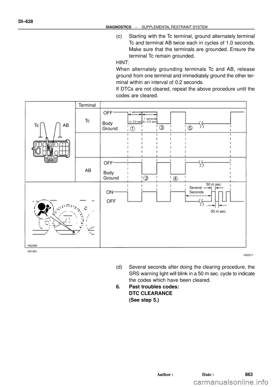
(c) Starting with the Tc terminal, ground alternately terminal
Tc and terminal AB twice each in cycles of 1.0 seconds.
Make sure that the terminals are grounded. Ensure the
terminal Tc remain grounded.
HINT:
When alternately grounding terminals Tc and AB, release
ground from one terminal and immediately ground the other ter-
minal within an interval of 0.2 seconds.
If DTCs are not cleared, repeat the above procedure until the
codes are cleared.
(d) Several seconds after doing the clearing procedure, the
SRS warning light will blink in a 50 m sec. cycle to indicate
the codes which have been cleared.
6. Past troubles codes:
DTC CLEARANCE
(See step 5.)
Page 2377 of 4592
H01461
H10313
H10314
ABTerminal
Tc
ABOFF
Body
Ground
OFF
ON
OFF
Several
Seconds50 m sec.
50 m sec.
1 seconds
(± 0.5 sec.)
Tc
Body
Ground
1 seconds
(± 0.5 sec.)
1
23
45
S05331
TOYOTA Hand±Held Tester
DLC3
± DIAGNOSTICSSUPPLEMENTAL RESTRAINT SYSTEM
DI±225
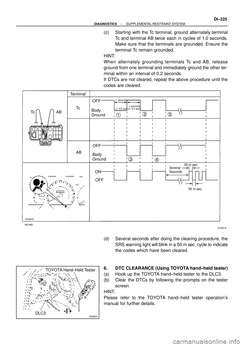
(c) Starting with the Tc terminal, ground alternately terminal
Tc and terminal AB twice each in cycles of 1.0 seconds.
Make sure that the terminals are grounded. Ensure the
terminal Tc remain grounded.
HINT:
When alternately grounding terminals Tc and AB, release
ground from one terminal and immediately ground the other ter-
minal within an interval of 0.2 seconds.
If DTCs are not cleared, repeat the above procedure until the
codes are cleared.
(d) Several seconds after doing the clearing procedure, the
SRS warning light will blink in a 50 m sec. cycle to indicate
the codes which have been cleared.
6. DTC CLEARANCE (Using TOYOTA hand±held tester)
(a) Hook up the TOYOTA hand±held tester to the DLC3.
(b) Clear the DTCs by following the prompts on the tester
screen.
HINT:
Please refer to the TOYOTA hand±held tester operation's
manual for further details.
Page 2595 of 4592
Z02754
Z00052
Z00054
44.5°
EM0181
Margin Thickness EM±44
± ENGINE MECHANICAL (5S±FE)CYLINDER HEAD
1216 Author�: Date�:
6. INSPECT VALVE STEMS AND GUIDE BUSHINGS
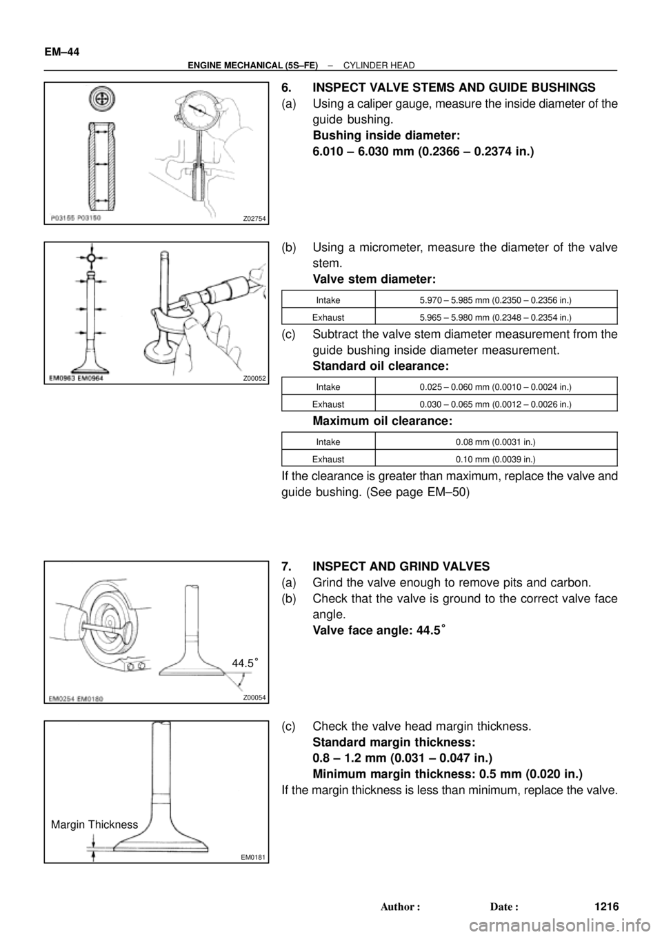
(a) Using a caliper gauge, measure the inside diameter of the
guide bushing.
Bushing inside diameter:
6.010 ± 6.030 mm (0.2366 ± 0.2374 in.)
(b) Using a micrometer, measure the diameter of the valve
stem.
Valve stem diameter:
Intake5.970 ± 5.985 mm (0.2350 ± 0.2356 in.)
Exhaust5.965 ± 5.980 mm (0.2348 ± 0.2354 in.)
(c) Subtract the valve stem diameter measurement from the
guide bushing inside diameter measurement.
Standard oil clearance:
Intake0.025 ± 0.060 mm (0.0010 ± 0.0024 in.)
Exhaust0.030 ± 0.065 mm (0.0012 ± 0.0026 in.)
Maximum oil clearance:
Intake0.08 mm (0.0031 in.)
Exhaust0.10 mm (0.0039 in.)
If the clearance is greater than maximum, replace the valve and
guide bushing. (See page EM±50)
7. INSPECT AND GRIND VALVES
(a) Grind the valve enough to remove pits and carbon.
(b) Check that the valve is ground to the correct valve face
angle.
Valve face angle: 44.5°
(c) Check the valve head margin thickness.
Standard margin thickness:
0.8 ± 1.2 mm (0.031 ± 0.047 in.)
Minimum margin thickness: 0.5 mm (0.020 in.)
If the margin thickness is less than minimum, replace the valve.
Page 2710 of 4592
P12754
Z00052
Z00054
44.5°
EM0181
Margin Thickness
± ENGINE MECHANICAL (1MZ±FE)CYLINDER HEAD
EM±45
1331 Author�: Date�:
9. INSPECT VALVE STEMS AND GUIDE BUSHINGS
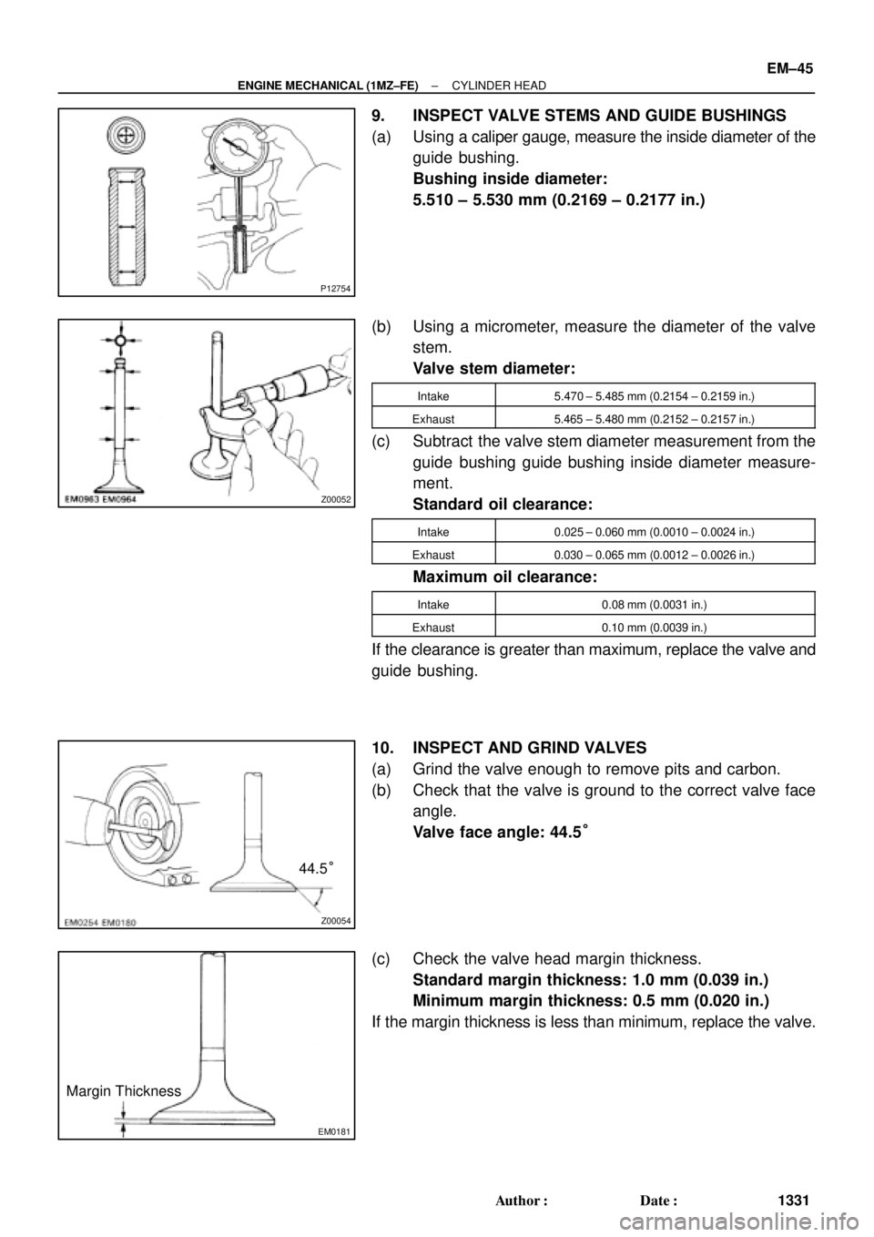
(a) Using a caliper gauge, measure the inside diameter of the
guide bushing.
Bushing inside diameter:
5.510 ± 5.530 mm (0.2169 ± 0.2177 in.)
(b) Using a micrometer, measure the diameter of the valve
stem.
Valve stem diameter:
Intake5.470 ± 5.485 mm (0.2154 ± 0.2159 in.)
Exhaust5.465 ± 5.480 mm (0.2152 ± 0.2157 in.)
(c) Subtract the valve stem diameter measurement from the
guide bushing guide bushing inside diameter measure-
ment.
Standard oil clearance:
Intake0.025 ± 0.060 mm (0.0010 ± 0.0024 in.)
Exhaust0.030 ± 0.065 mm (0.0012 ± 0.0026 in.)
Maximum oil clearance:
Intake0.08 mm (0.0031 in.)
Exhaust0.10 mm (0.0039 in.)
If the clearance is greater than maximum, replace the valve and
guide bushing.
10. INSPECT AND GRIND VALVES
(a) Grind the valve enough to remove pits and carbon.
(b) Check that the valve is ground to the correct valve face
angle.
Valve face angle: 44.5°
(c) Check the valve head margin thickness.
Standard margin thickness: 1.0 mm (0.039 in.)
Minimum margin thickness: 0.5 mm (0.020 in.)
If the margin thickness is less than minimum, replace the valve.
Page 2794 of 4592
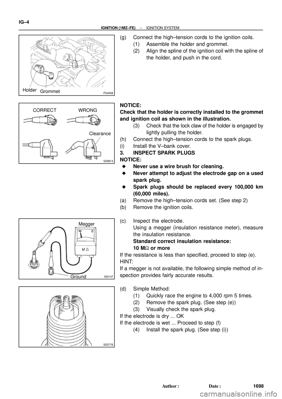
P24458HolderGrommet
S00813
CORRECT WRONG
Clearance
IG0147
Megger
Ground
S03776
IG±4
± IGNITION (1MZ±FE)IGNITION SYSTEM
1698 Author�: Date�:
(g) Connect the high±tension cords to the ignition coils.
(1) Assemble the holder and grommet.
(2) Align the spline of the ignition coil with the spline of
the holder, and push in the cord.
NOTICE:
Check that the holder is correctly installed to the grommet
and ignition coil as shown in the illustration.
(3) Check that the lock claw of the holder is engaged by
lightly pulling the holder.
(h) Connect the high±tension cords to the spark plugs.
(i) Install the V±bank cover.
3. INSPECT SPARK PLUGS
NOTICE:
�Never use a wire brush for cleaning.
�Never attempt to adjust the electrode gap on a used
spark plug.
�Spark plugs should be replaced every 100,000 km
(60,000 miles).
(a) Remove the high±tension cords set. (See step 2)
(b) Remove the ignition coils.
(c) Inspect the electrode.
Using a megger (insulation resistance meter), measure
the insulation resistance.
Standard correct insulation resistance:
10 MW or more
If the resistance is less than specified, proceed to step (e).
HINT:
If a megger is not available, the following simple method of in-
spection provides fairly accurate results.
(d) Simple Method:
(1) Quickly race the engine to 4,000 rpm 5 times.
(2) Remove the spark plug. (See step (e))
(3) Visually check the spark plug.
If the electrode is dry ... OK
If the electrode is wet ... Proceed to step (f)
(4) Install the spark plug. (See step (i))