Page 111 of 4592
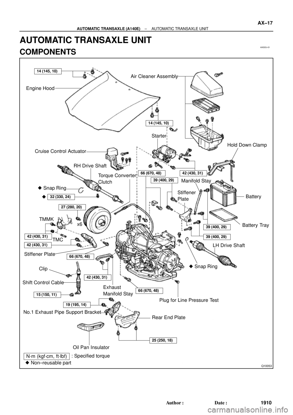
AX03G±01
Q10053
14 (145, 10)
No.1 Exhaust Pipe Support BracketClip Engine Hood
Air Cleaner Assembly
14 (145, 10)
Starter
Cruise Control Actuator
RH Drive Shaft
42 (430, 31)66 (670, 48)
39 (400, 29)
39 (400, 29)
39 (400, 29)
Hold Down Clamp
Manifold Stay
Stiffener
PlateBattery
Battery Tray � Snap Ring
�
32 (330, 24)
27 (280, 20)
Torque Converter
Clutch
x6
42 (430, 31)
42 (430, 31)
Stiffener Plate66 (670, 48)
42 (430, 31)
Exhaust
Manifold Stay66 (670, 48)
� Snap RingLH Drive Shaft
Plug for Line Pressure Test
Rear End Plate
15 (150, 11)
19 (195, 14)
25 (250, 18)
Oil Pan Insulator Shift Control Cable
N´m (kgf´cm, ft´lbf): Specified torque
� Non±reusable partTMMK
TMC
± AUTOMATIC TRANSAXLE (A140E)AUTOMATIC TRANSAXLE UNIT
AX±17
1910 Author�: Date�:
AUTOMATIC TRANSAXLE UNIT
COMPONENTS
Page 113 of 4592

AX03H±01
Q10055
Q00211
Q10056
Q10057
± AUTOMATIC TRANSAXLE (A140E)AUTOMATIC TRANSAXLE UNIT
AX±19
1912 Author�: Date�:
REMOVAL
1. REMOVE BATTERY
2. REMOVE AIR CLEANER ASSEMBLY
3. DISCONNECT THROTTLE CABLE
4. w/ CRUISE CONTROL:
REMOVE CRUISE CONTROL ACTUATOR
(a) Disconnect the connector.
(b) Remove the 3 bolts and disconnect cruise control actua-
tor with the bracket.
5. DISCONNECT OIL COOLER HOSE
6. DISCONNECT VEHICLE SPEED SENSOR CONNEC-
TOR
7. DISCONNECT PARK/NEUTRAL POSITION SWITCH
CONNECTOR
8. DISCONNECT SHIFT SOLENOID VALVE NO.1 AND
NO.2 CONNECTOR
9. DISCONNECT SHIFT SOLENOID VALVE SL CONNEC-
TOR
10. REMOVE 2 FRONT SIDE ENGINE MOUNTING BOLTS
Torque:
TMC made: 80 N´m (820 kgf´cm, 59 ft´lbf)
TMMK made:
Green color bolt: 66 N´m (670 kgf´cm, 48 ft´lbf)
Silver color bolt: 44 N´m (450 kgf´cm, 32 ft´lbf)
11. DISCONNECT 2 GROUND CABLES
12. REMOVE STARTER
(a) Disconnect the connector and remove the nut.
(b) Remove the 2 bolts, shift cable clamp and starter.
Torque: 39 N´m (400 kgf´cm, 29 ft´lbf)
13. REMOVE 3 TRANSAXLE±TO±ENGINE BOLTS
Torque: 66 N´m (670 kgf´cm, 48 ft´lbf)
Page 134 of 4592
Q09982
AX03R±01
Q00225
Q00270
Q00270
Q057310.8 ± 1.5 mm (0.031±0.059 in.)200 mm
(7.87 in.)
± AUTOMATIC TRANSAXLE (A541E)THROTTLE CABLE
AX±13
1933 Author�: Date�:
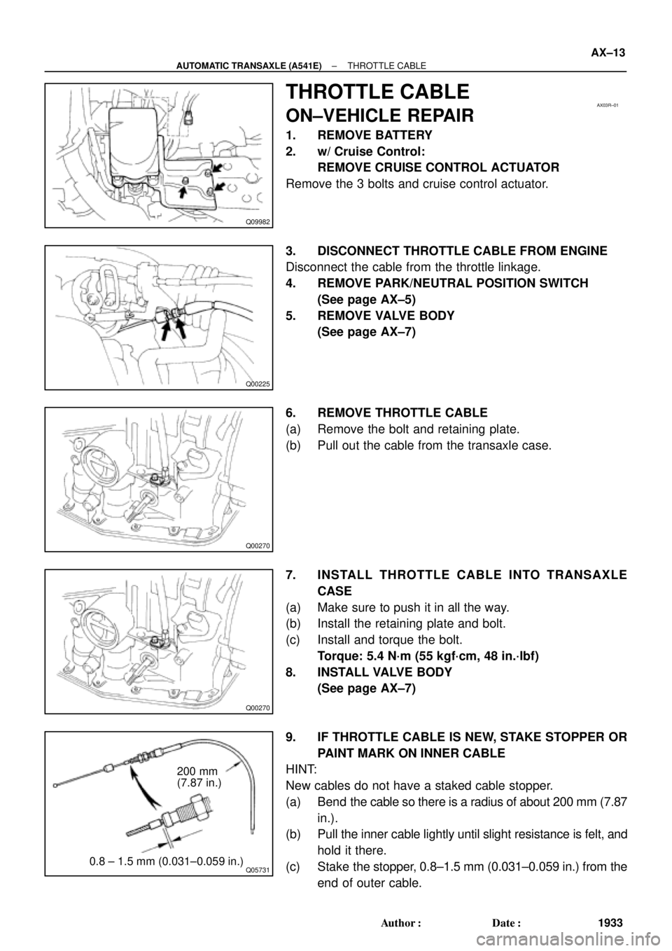
THROTTLE CABLE
ON±VEHICLE REPAIR
1. REMOVE BATTERY
2. w/ Cruise Control:
REMOVE CRUISE CONTROL ACTUATOR
Remove the 3 bolts and cruise control actuator.
3. DISCONNECT THROTTLE CABLE FROM ENGINE
Disconnect the cable from the throttle linkage.
4. REMOVE PARK/NEUTRAL POSITION SWITCH
(See page AX±5)
5. REMOVE VALVE BODY
(See page AX±7)
6. REMOVE THROTTLE CABLE
(a) Remove the bolt and retaining plate.
(b) Pull out the cable from the transaxle case.
7. INSTALL THROTTLE CABLE INTO TRANSAXLE
CASE
(a) Make sure to push it in all the way.
(b) Install the retaining plate and bolt.
(c) Install and torque the bolt.
Torque: 5.4 N´m (55 kgf´cm, 48 in.´lbf)
8. INSTALL VALVE BODY
(See page AX±7)
9. IF THROTTLE CABLE IS NEW, STAKE STOPPER OR
PAINT MARK ON INNER CABLE
HINT:
New cables do not have a staked cable stopper.
(a) Bend the cable so there is a radius of about 200 mm (7.87
in.).
(b) Pull the inner cable lightly until slight resistance is felt, and
hold it there.
(c) Stake the stopper, 0.8±1.5 mm (0.031±0.059 in.) from the
end of outer cable.
Page 135 of 4592
Q00225
Q09982
AX±14
± AUTOMATIC TRANSAXLE (A541E)THROTTLE CABLE
1934 Author�: Date�:
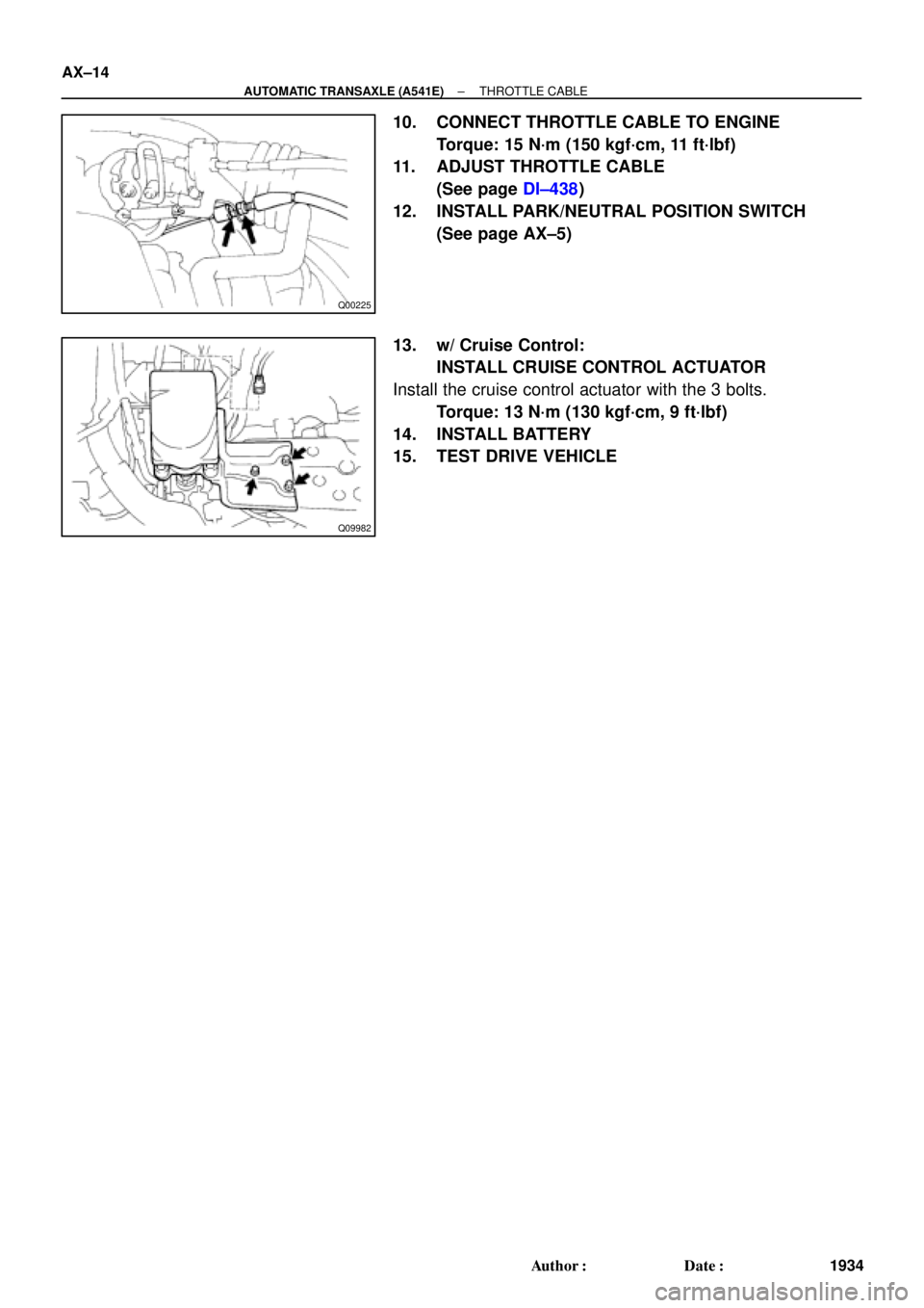
10. CONNECT THROTTLE CABLE TO ENGINE
Torque: 15 N´m (150 kgf´cm, 11 ft´lbf)
11. ADJUST THROTTLE CABLE
(See page DI±438)
12. INSTALL PARK/NEUTRAL POSITION SWITCH
(See page AX±5)
13. w/ Cruise Control:
INSTALL CRUISE CONTROL ACTUATOR
Install the cruise control actuator with the 3 bolts.
Torque: 13 N´m (130 kgf´cm, 9 ft´lbf)
14. INSTALL BATTERY
15. TEST DRIVE VEHICLE
Page 142 of 4592
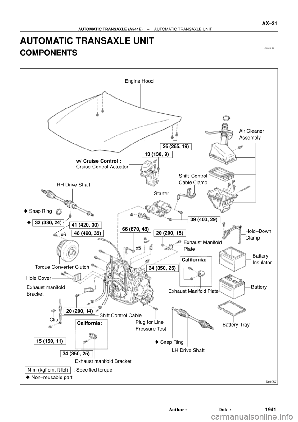
AX03X±01
D01057
Engine Hood
Cruise Control Actuator
RH Drive ShaftAir Cleaner
Assembly
Shift Control Cable
LH Drive Shaft Plug for Line
Pressure TestBattery TrayBatteryBattery
Insulator � Snap Ring
Exhaust manifold
Bracket Hole CoverTorque Converter ClutchShift Control
Cable Clamp
Starter
x6
ClipHold±Down
Clamp
26 (265, 19)
15 (150, 11)
34 (350, 25)
39 (400, 29)
66 (670, 48)48 (490, 35)
32 (330, 24)41 (420, 30)
N´m (kgf´cm, ft´lbf) : Specified torque
� Non±reusable part� Snap Ring �
20 (200, 15)
20 (200, 14)
13 (130, 9)
x5Exhaust Manifold
Plate w/ Cruise Control :
California:
Exhaust Manifold Plate
34 (350, 25)
Exhaust manifold Bracket
California:
± AUTOMATIC TRANSAXLE (A541E)AUTOMATIC TRANSAXLE UNIT
AX±21
1941 Author�: Date�:
AUTOMATIC TRANSAXLE UNIT
COMPONENTS
Page 144 of 4592
AX03Y±01
Q00225
Q09982
Q10287
Q00075
Q10028
± AUTOMATIC TRANSAXLE (A541E)AUTOMATIC TRANSAXLE UNIT
AX±23
1943 Author�: Date�:
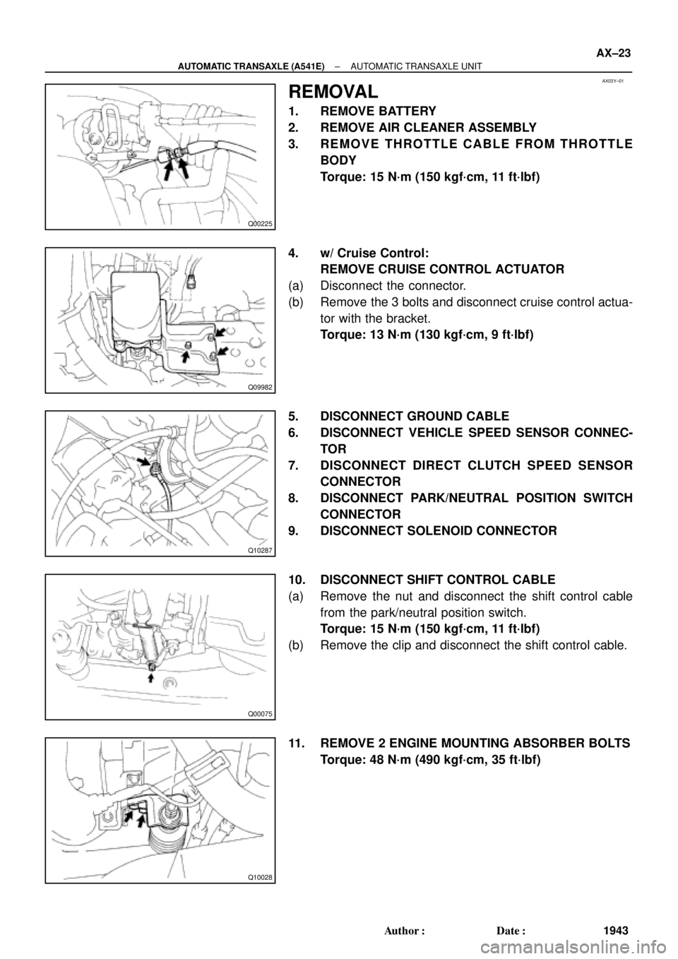
REMOVAL
1. REMOVE BATTERY
2. REMOVE AIR CLEANER ASSEMBLY
3. REMOVE THROTTLE CABLE FROM THROTTLE
BODY
Torque: 15 N´m (150 kgf´cm, 11 ft´lbf)
4. w/ Cruise Control:
REMOVE CRUISE CONTROL ACTUATOR
(a) Disconnect the connector.
(b) Remove the 3 bolts and disconnect cruise control actua-
tor with the bracket.
Torque: 13 N´m (130 kgf´cm, 9 ft´lbf)
5. DISCONNECT GROUND CABLE
6. DISCONNECT VEHICLE SPEED SENSOR CONNEC-
TOR
7. DISCONNECT DIRECT CLUTCH SPEED SENSOR
CONNECTOR
8. DISCONNECT PARK/NEUTRAL POSITION SWITCH
CONNECTOR
9. DISCONNECT SOLENOID CONNECTOR
10. DISCONNECT SHIFT CONTROL CABLE
(a) Remove the nut and disconnect the shift control cable
from the park/neutral position switch.
Torque: 15 N´m (150 kgf´cm, 11 ft´lbf)
(b) Remove the clip and disconnect the shift control cable.
11. REMOVE 2 ENGINE MOUNTING ABSORBER BOLTS
Torque: 48 N´m (490 kgf´cm, 35 ft´lbf)
Page 588 of 4592
± BODY ELECTRICALBODY ELECTRICAL SYSTEM
BE±7
2227 Author�: Date�:
Seat Belt warning light does not light up.
1. Bulb
2. Seat Belt Buckle Switch
3. Integration Relay (I/P J/B No.1)
4. Wire Harness±
BE±47
BE±47
±
Discharge warning light does not light up.
1. IGN Fuse (I/P J/B No.1)
2. Bulb
3. Wire Harness
4. Generator (5S±FE)
(1MZ±FE)±
±
±
CH±1
CH±1
Light Failure warning light does not light up.
1. Bulb
2. Light Failure Sensor
3. Bulb Check Relay
4. Wire Harness
5. Taillight system±
BE±37
BE±47
±
BE±24
Brake warning light does not light up.
1. Bulb
2. Parking Brake Switch
3. Brake Fluid Level Warning Switch
4. Bulb Check Relay
5. Meter Circuit Plate
6. Wire Harness±
BE±47
BE±47
BE±47
BE±46
±
SRS Warning light does not light up.
1. ECU±B Fuse (E/G Room J/B No.2)
2. Bulb
3. Airbag Sensor Assembly
4. Meter Circuit Plate
5. Wire Harness±
±
DI±626
BE±46
±
Open Door warning light does not light up.
1. DOME Fuse (E/G Room J/B No.2)
2. Bulb
3. Door Courtesy Switch
4. Meter Circuit Plate
5. Wire Harness±
±
BE±32
BE±46
±
Washer Level warning light does not light up.
1. Bulb
2. Washer Fluid Level Warning Switch
3. Meter Circuit Plate
4. Wire Harness±
BE±47
BE±46
±
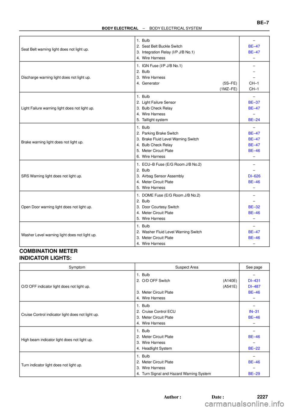
COMBINATION METER
INDICATOR LIGHTS:
SymptomSuspect AreaSee page
O/D OFF indicator light does not light up.
1. Bulb
2. O/D OFF Switch (A140E)
(A541E)
3. Meter Circuit Plate
4. Wire Harness±
DI±431
DI±487
BE±46
±
Cruise Control indicator light does not light up.
1. Bulb
2. Cruise Control ECU
3. Meter Circuit Plate
4. Wire Harness±
IN±31
BE±46
±
High beam indicator light does not light up.
1. Bulb
2. Meter Circuit Plate
3. Wire Harness
4. Headlight System±
BE±46
±
BE±22
Turn indicator light does not light up.
1. Bulb
2. Meter Circuit Plate
3. Wire Harness
4. Turn Signal and Hazard Warning System±
BE±46
±
BE±29
Page 618 of 4592
BE0AF±02
N18026
FreePushed in
FreePushed in w/o Cruise control:
w/ Cruise control:1 2
3 1
2
4
N20208
1
2
± BODY ELECTRICALSTOP LIGHT SYSTEM
BE±37
2257 Author�: Date�:
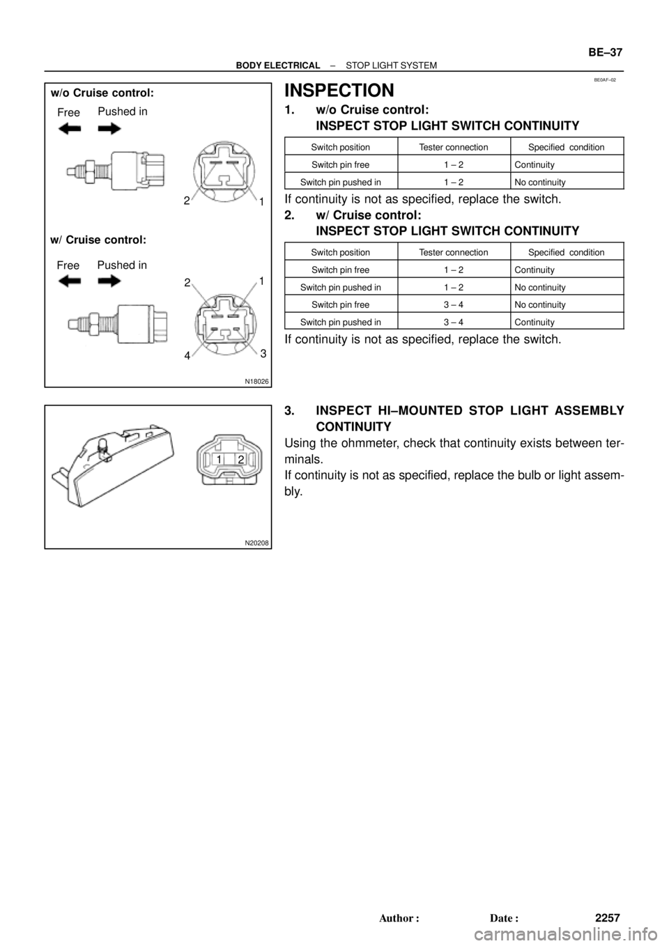
INSPECTION
1. w/o Cruise control:
INSPECT STOP LIGHT SWITCH CONTINUITY
Switch positionTester connectionSpecified condition
Switch pin free1 ± 2Continuity
Switch pin pushed in1 ± 2No continuity
If continuity is not as specified, replace the switch.
2. w/ Cruise control:
INSPECT STOP LIGHT SWITCH CONTINUITY
Switch positionTester connectionSpecified condition
Switch pin free1 ± 2Continuity
Switch pin pushed in1 ± 2No continuity
Switch pin free3 ± 4No continuity
Switch pin pushed in3 ± 4Continuity
If continuity is not as specified, replace the switch.
3. INSPECT HI±MOUNTED STOP LIGHT ASSEMBLY
CONTINUITY
Using the ohmmeter, check that continuity exists between ter-
minals.
If continuity is not as specified, replace the bulb or light assem-
bly.