Page 1675 of 4592
D01092
Transaxle
*1: Except California, w/ Engine Immobilizer and / or TRAC
*2: California, w/ Engine Immobilizer and / or TRACShift Solenoid
Valve No.1
W3
6 E3
L±B BV
J/C J26
A*2 *1
Shift Solenoid
Valve No.2
E3A
AL±BE11
E10 7
11
817
E10
E11 *2 *1ECM
B+
S1
S2B+
Cruise Control ECU
Q07642D00833D01909
California, w/ Engine Immobilizer
and / or TRAC:S1
S2
S1
S2
Except California, w/ Engine Immobilizer
and / or TRAC:
± DIAGNOSTICSAUTOMATIC TRANSAXLE (A541E)
DI±463
698 Author�: Date�:
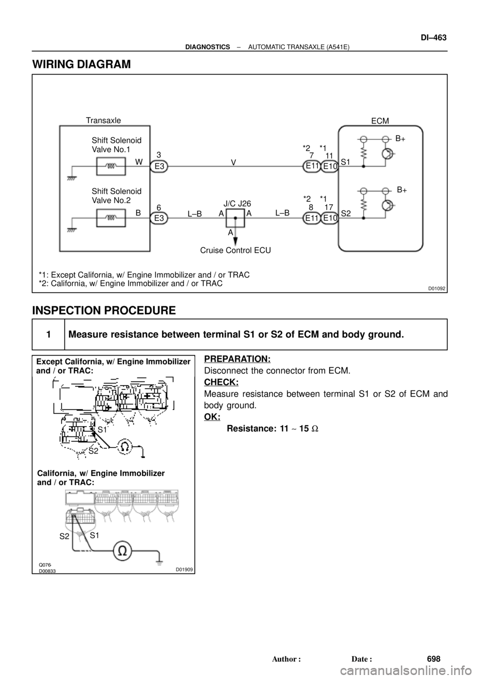
WIRING DIAGRAM
INSPECTION PROCEDURE
1 Measure resistance between terminal S1 or S2 of ECM and body ground.
PREPARATION:
Disconnect the connector from ECM.
CHECK:
Measure resistance between terminal S1 or S2 of ECM and
body ground.
OK:
Resistance: 11 ~ 15 W
Page 1696 of 4592
D01899
Cruise Control ECU
14
ODY±B7B+
OD1ECM
C15
E10E7
*1: Except California, w/ Engine Immobilizer and / or TRAC
*2: California, w/ Engine Immobilizer and / or TRAC*2
*1
24 DI±484
± DIAGNOSTICSAUTOMATIC TRANSAXLE (A541E)
719 Author�: Date�:
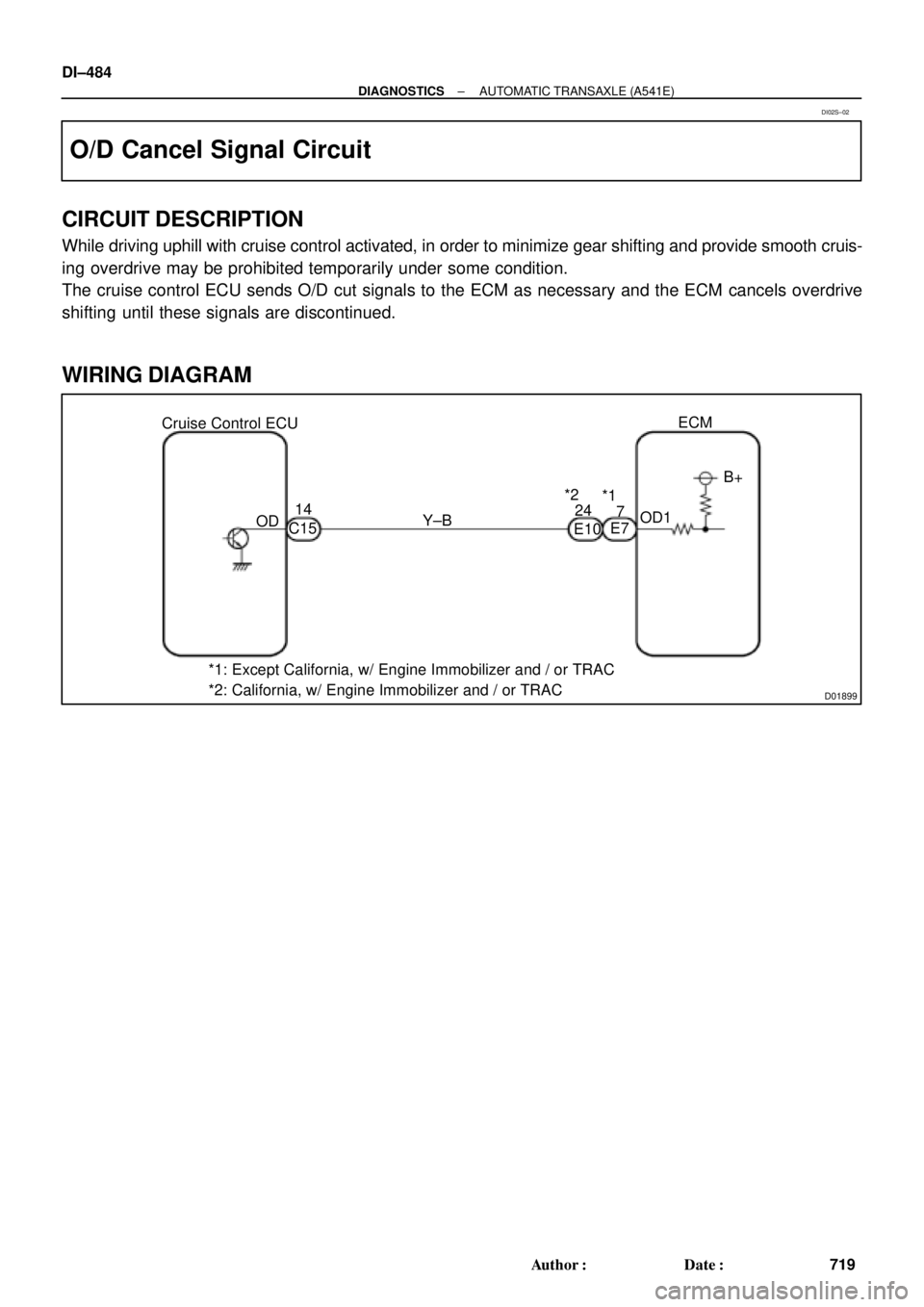
O/D Cancel Signal Circuit
CIRCUIT DESCRIPTION
While driving uphill with cruise control activated, in order to minimize gear shifting and provide smooth cruis-
ing overdrive may be prohibited temporarily under some condition.
The cruise control ECU sends O/D cut signals to the ECM as necessary and the ECM cancels overdrive
shifting until these signals are discontinued.
WIRING DIAGRAM
DI02S±02
Page 1698 of 4592
AB0119
N19917
I00742
ON
O/D
(±)
(+)
DI±486
± DIAGNOSTICSAUTOMATIC TRANSAXLE (A541E)
721 Author�: Date�:
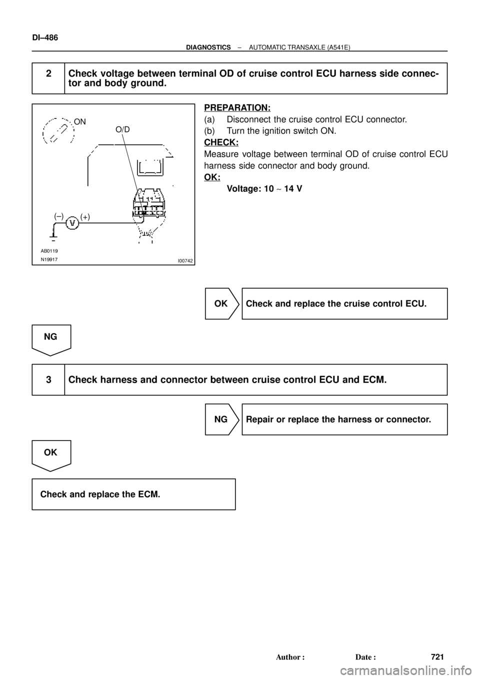
2 Check voltage between terminal OD of cruise control ECU harness side connec-
tor and body ground.
PREPARATION:
(a) Disconnect the cruise control ECU connector.
(b) Turn the ignition switch ON.
CHECK:
Measure voltage between terminal OD of cruise control ECU
harness side connector and body ground.
OK:
Voltage: 10 ~ 14 V
OK Check and replace the cruise control ECU.
NG
3 Check harness and connector between cruise control ECU and ECM.
NG Repair or replace the harness or connector.
OK
Check and replace the ECM.
Page 2080 of 4592
DI08F±11
Customer Problem Analysis
Check and Clear DTC (Precheck)
Vehicle Brought to Workshop
Problem Symptom ConfirmationSymptom Simulation Symptom does not occur
DTC CheckNormal code
DTC Chart
Problem Symptoms Table
Circuit InspectionInput Signal Check
Parts Inspection
Identification of Problem
Repair
Confirmation Test
EndItems inside
are titles of pages in this
manual with the page number indicated in the
bottom portion. See the indicated pages
for detailed explanations. 1
2
34
5
6
7
89
10
Step 2, 5: Diagnostic steps permitting the use
of the TOYOTA hand±held tester or
TOYOTA break±out±box. P. DI±869
P. DI±870
P. DI±870
P. DI±875
P. IN±21
P. DI±879
P. DI±881
OKNG
Symptom occurs
Malfunction code DI±868
± DIAGNOSTICSCRUISE CONTROL SYSTEM
1103 Author�: Date�:
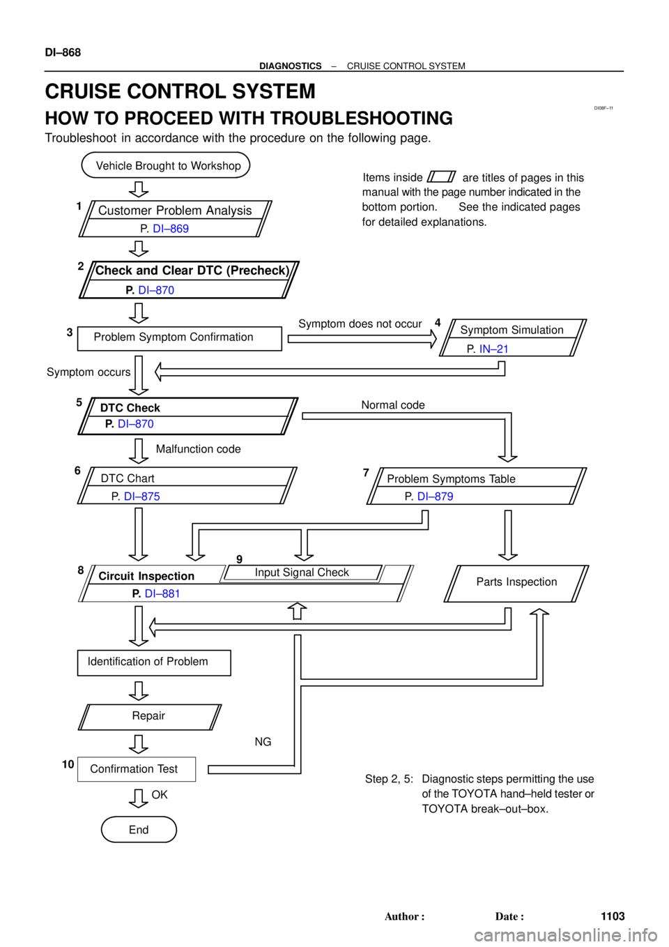
CRUISE CONTROL SYSTEM
HOW TO PROCEED WITH TROUBLESHOOTING
Troubleshoot in accordance with the procedure on the following page.
Page 2081 of 4592

DI08G±08
CRUISE CONTROL SYSTEM Check Sheet
Inspector 's name:
Customer 's Name
Date VehicleRegistration No.
Registration Year
Frame No.
Odometer Reading / /km
Mile
Condition of
Problem Occurrence
Date of Problem
How Often does
Occurrence
Problem Occurs
Vehicle Speed when
Problem Occurred / /
Continuous Intermittent ( Times a day)
km
Mile Brought in
Auto cancel
occurs� Driving condition
� City driving � Freeway � Up hill � Down hill
� After cancel occurred, did the driver activate cruise control
again?
� Yes � No
� Cancel does not
occur� With brake ON
� Except D position shift � At 40 km/h (25 mph) or less
� When control SW turns to CANCEL position
� Cruise control
malfunction� Slip to acceleration side
� Slip to deceleration side
� Hunting occurs
� O/D cut off does not occur
� O/D does not return
� Switch
malfunction� SET � ACCEL � COAST � RESUME � CANCEL
�
� Remains ON � Does not light up � Blinking Symptoms
DTC Check1st Time2nd Time
� Normal Code � Malfunction Code (Code )
� Normal Code � Malfunction Code (Code )
± DIAGNOSTICSCRUISE CONTROL SYSTEM
DI±869
1104 Author�: Date�:
CUSTOMER PROBLEM ANALYSIS CHECK
Page 2082 of 4592
I00279CRUISE MAIN Indicator Light
DI1KS±03
BE4034
Indicator light
1.5 sec.0.5 sec.
ON
OFF
I00169
DLC2
Tc E 1
DI±870
± DIAGNOSTICSCRUISE CONTROL SYSTEM
1105 Author�: Date�:
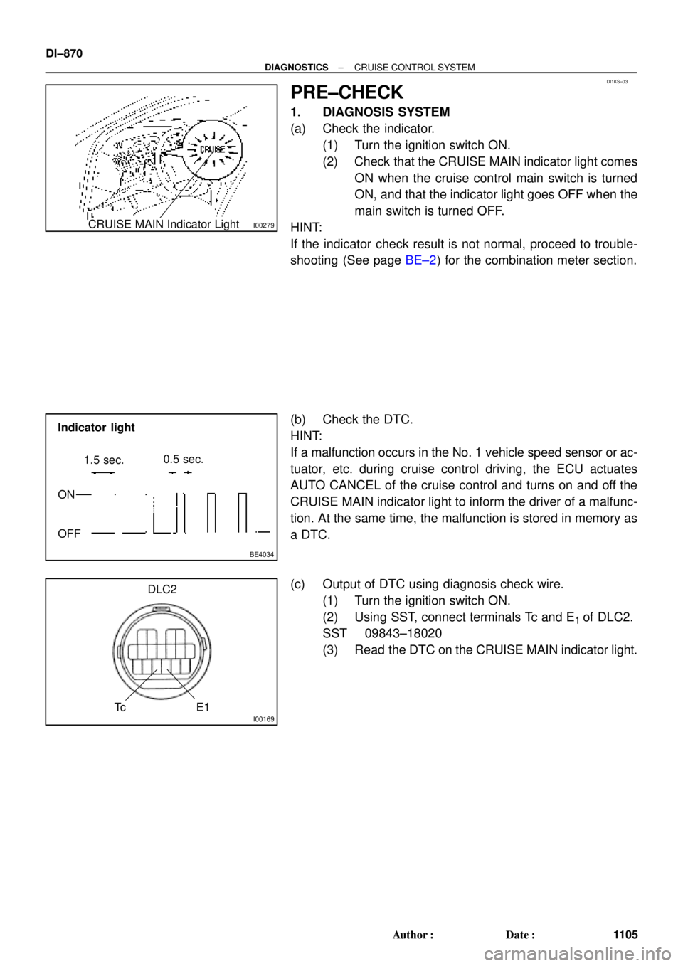
PRE±CHECK
1. DIAGNOSIS SYSTEM
(a) Check the indicator.
(1) Turn the ignition switch ON.
(2) Check that the CRUISE MAIN indicator light comes
ON when the cruise control main switch is turned
ON, and that the indicator light goes OFF when the
main switch is turned OFF.
HINT:
If the indicator check result is not normal, proceed to trouble-
shooting (See page BE±2) for the combination meter section.
(b) Check the DTC.
HINT:
If a malfunction occurs in the No. 1 vehicle speed sensor or ac-
tuator, etc. during cruise control driving, the ECU actuates
AUTO CANCEL of the cruise control and turns on and off the
CRUISE MAIN indicator light to inform the driver of a malfunc-
tion. At the same time, the malfunction is stored in memory as
a DTC.
(c) Output of DTC using diagnosis check wire.
(1) Turn the ignition switch ON.
(2) Using SST, connect terminals Tc and E
1 of DLC2.
SST 09843±18020
(3) Read the DTC on the CRUISE MAIN indicator light.
Page 2083 of 4592
BE4032
BE4033I00021
Normal code
0.25 sec.
0.25 sec.
ON
OFF
ON
OFF
4 sec.1.5 sec. 0.5 sec.
2.5 sec.0.5 sec.1.5 sec.
Malfunction codes 11 and 21
Code 11 Code 21
H07517
I08438
DLC1
TC
E1(b) (d) 5 times
within 3 seconds
(c)
± DIAGNOSTICSCRUISE CONTROL SYSTEM
DI±871
1106 Author�: Date�:
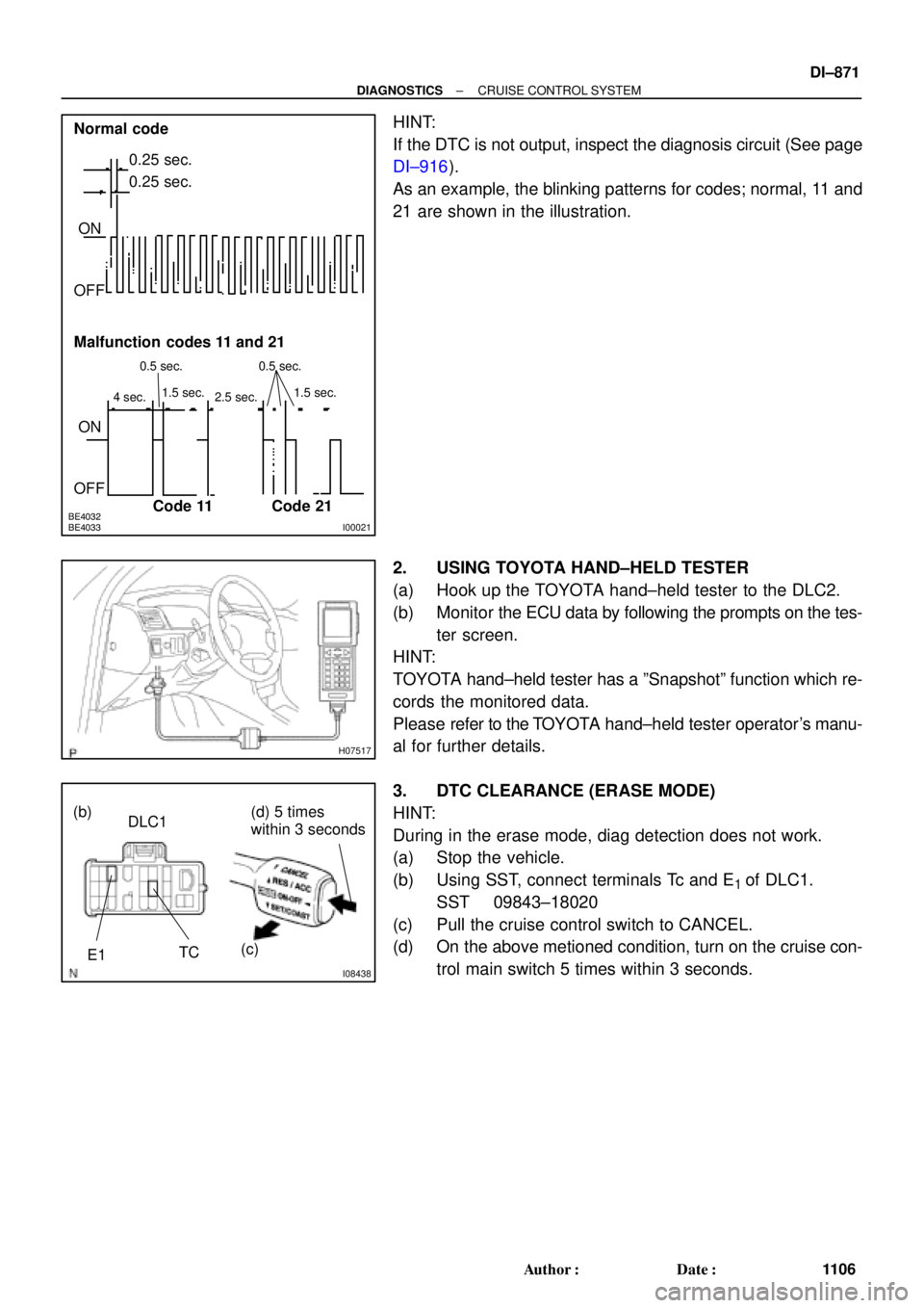
HINT:
If the DTC is not output, inspect the diagnosis circuit (See page
DI±916).
As an example, the blinking patterns for codes; normal, 11 and
21 are shown in the illustration.
2. USING TOYOTA HAND±HELD TESTER
(a) Hook up the TOYOTA hand±held tester to the DLC2.
(b) Monitor the ECU data by following the prompts on the tes-
ter screen.
HINT:
TOYOTA hand±held tester has a ºSnapshotº function which re-
cords the monitored data.
Please refer to the TOYOTA hand±held tester operator's manu-
al for further details.
3. DTC CLEARANCE (ERASE MODE)
HINT:
During in the erase mode, diag detection does not work.
(a) Stop the vehicle.
(b) Using SST, connect terminals Tc and E
1 of DLC1.
SST 09843±18020
(c) Pull the cruise control switch to CANCEL.
(d) On the above metioned condition, turn on the cruise con-
trol main switch 5 times within 3 seconds.
Page 2084 of 4592
N17520
N17520
N17520
DI±872
± DIAGNOSTICSCRUISE CONTROL SYSTEM
1107 Author�: Date�:
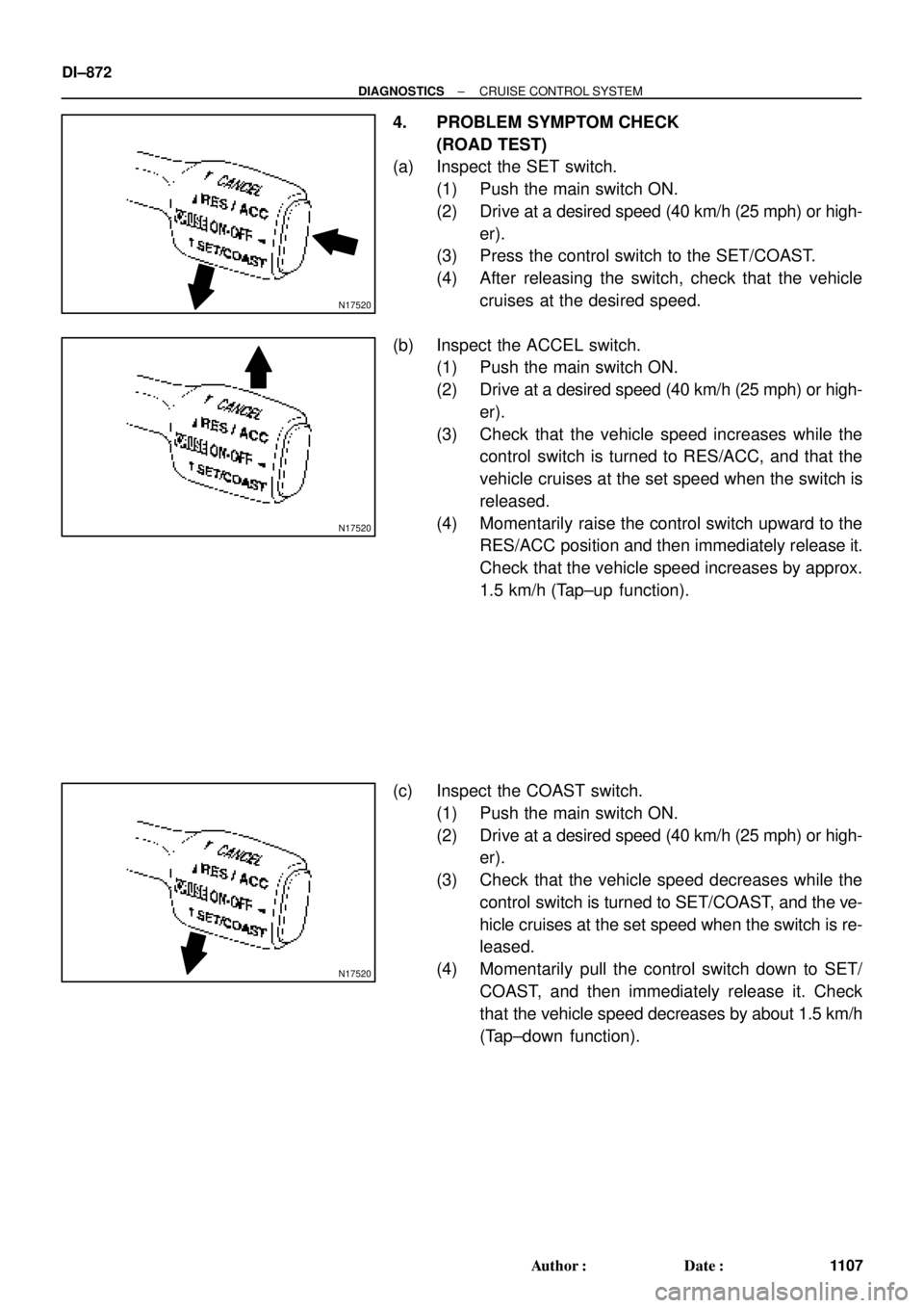
4. PROBLEM SYMPTOM CHECK
(ROAD TEST)
(a) Inspect the SET switch.
(1) Push the main switch ON.
(2) Drive at a desired speed (40 km/h (25 mph) or high-
er).
(3) Press the control switch to the SET/COAST.
(4) After releasing the switch, check that the vehicle
cruises at the desired speed.
(b) Inspect the ACCEL switch.
(1) Push the main switch ON.
(2) Drive at a desired speed (40 km/h (25 mph) or high-
er).
(3) Check that the vehicle speed increases while the
control switch is turned to RES/ACC, and that the
vehicle cruises at the set speed when the switch is
released.
(4) Momentarily raise the control switch upward to the
RES/ACC position and then immediately release it.
Check that the vehicle speed increases by approx.
1.5 km/h (Tap±up function).
(c) Inspect the COAST switch.
(1) Push the main switch ON.
(2) Drive at a desired speed (40 km/h (25 mph) or high-
er).
(3) Check that the vehicle speed decreases while the
control switch is turned to SET/COAST, and the ve-
hicle cruises at the set speed when the switch is re-
leased.
(4) Momentarily pull the control switch down to SET/
COAST, and then immediately release it. Check
that the vehicle speed decreases by about 1.5 km/h
(Tap±down function).