Page 2 of 4592
AC±2
± AIR CONDITIONINGAIR CONDITIONING SYSTEM
2484 Author�: Date�:
9. SUPPLEMENTAL RESTRAINT SYSTEM (SRS)
The CAMRY is equipped with an SRS (Supplemental Restraint
System) such as the driver airbag and passenger airbag. Fail-
ure to carry out service operations the correct sequence could
cause the SRS to unexpectedly deployed during servicing, pos-
sible the SRS may fail to operate when required. Before servic-
ing (including removal or installation of parts, inspection or re-
placement), be sure to read the following item carefully, then
follow the correct procedure described in the repair manual.
Page 10 of 4592
AC0LJ±03
N13795
Quick Disconnect
Adapter
Charging
Service ValveHose
N13794
Vacuum Pump
Vacuum Pump Adapter
N13791
Low Pressure
Service Valve
Vacuum Pump Adapter High Pressure
Service ValveManifold
Gauge
Set
AC±10
± AIR CONDITIONINGAIR CONDITIONING SYSTEM
2492 Author�: Date�:
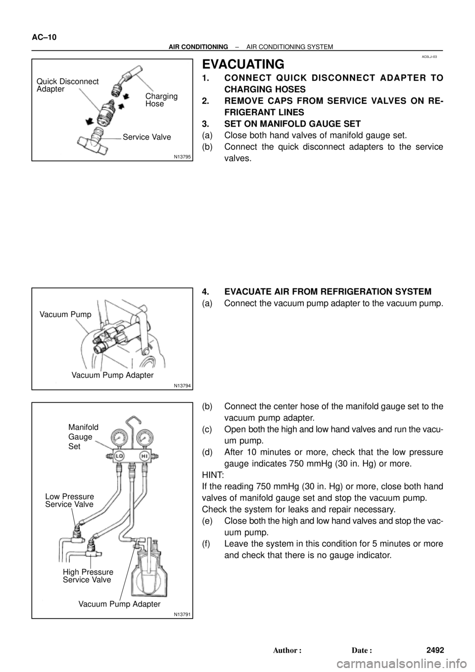
EVACUATING
1. CONNECT QUICK DISCONNECT ADAPTER TO
CHARGING HOSES
2. REMOVE CAPS FROM SERVICE VALVES ON RE-
FRIGERANT LINES
3. SET ON MANIFOLD GAUGE SET
(a) Close both hand valves of manifold gauge set.
(b) Connect the quick disconnect adapters to the service
valves.
4. EVACUATE AIR FROM REFRIGERATION SYSTEM
(a) Connect the vacuum pump adapter to the vacuum pump.
(b) Connect the center hose of the manifold gauge set to the
vacuum pump adapter.
(c) Open both the high and low hand valves and run the vacu-
um pump.
(d) After 10 minutes or more, check that the low pressure
gauge indicates 750 mmHg (30 in. Hg) or more.
HINT:
If the reading 750 mmHg (30 in. Hg) or more, close both hand
valves of manifold gauge set and stop the vacuum pump.
Check the system for leaks and repair necessary.
(e) Close both the high and low hand valves and stop the vac-
uum pump.
(f) Leave the system in this condition for 5 minutes or more
and check that there is no gauge indicator.
Page 11 of 4592
AC21S±01
N13793
Charging Cylinder High Pressure
Service Valve Low Pressure
Service ValvePush
Air
N13792
Gas Leak
Detector
± AIR CONDITIONINGAIR CONDITIONING SYSTEM
AC±11
2493 Author�: Date�:
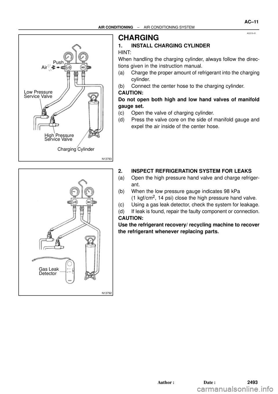
CHARGING
1. INSTALL CHARGING CYLINDER
HINT:
When handling the charging cylinder, always follow the direc-
tions given in the instruction manual.
(a) Charge the proper amount of refrigerant into the charging
cylinder.
(b) Connect the center hose to the charging cylinder.
CAUTION:
Do not open both high and low hand valves of manifold
gauge set.
(c) Open the valve of charging cylinder.
(d) Press the valve core on the side of manifold gauge and
expel the air inside of the center hose.
2. INSPECT REFRIGERATION SYSTEM FOR LEAKS
(a) Open the high pressure hand valve and charge refriger-
ant.
(b) When the low pressure gauge indicates 98 kPa
(1 kgf/cm
2, 14 psi) close the high pressure hand valve.
(c) Using a gas leak detector, check the system for leakage.
(d) If leak is found, repair the faulty component or connection.
CAUTION:
Use the refrigerant recovery/ recycling machine to recover
the refrigerant whenever replacing parts.
Page 12 of 4592

N13790
Low Pressure
Service Valve
High Pressure
Service Valve
I07055
Properly
Charged
Insufficiently
Charged AC±12
± AIR CONDITIONINGAIR CONDITIONING SYSTEM
2494 Author�: Date�:
3. CHARGE REFRIGERANT INTO REFRIGERANT SYS-
TEM
If there is no leak after refrigerant leak check, charge the proper
amount of refrigerant into refrigeration system.
CAUTION:
�Never run the engine when charging the system
through the high pressure side.
�Do not open the low pressure hand valve when the
system is being charged with liquid refrigerant.
(a) Open the high pressure hand valve fully.
(b) Charge specified amount of refrigerant, then close the
high pressure hand valve.
HINT:
A fully charged system is indicated by the sight glass being free
of any bubbles.
(c) Charge partially refrigeration system with refrigerant.
(1) Set vehicle in these conditions:
�Running engine at 1,500 rpm
�Blower speed control set at ºHIº
�Temperature control set at ºMAX. COOLº
�Air inlet control set at ºRECIRCº
�Fully open doors (Sliding roof: closed)
(2) Open the low pressure hand valve.
CAUTION:
Do not open the high pressure hand valve.
(d) Charge refrigerant until bubbles disappear and check the
pressure on the gauge through the sight glass.
Page 19 of 4592
N20312
High Pressure
Charging hose Low Pressure
Charging Hose
AC0LP±02
N04392
Sleeve
± AIR CONDITIONINGMANIFOLD GAUGE SET
AC±19
2501 Author�: Date�:
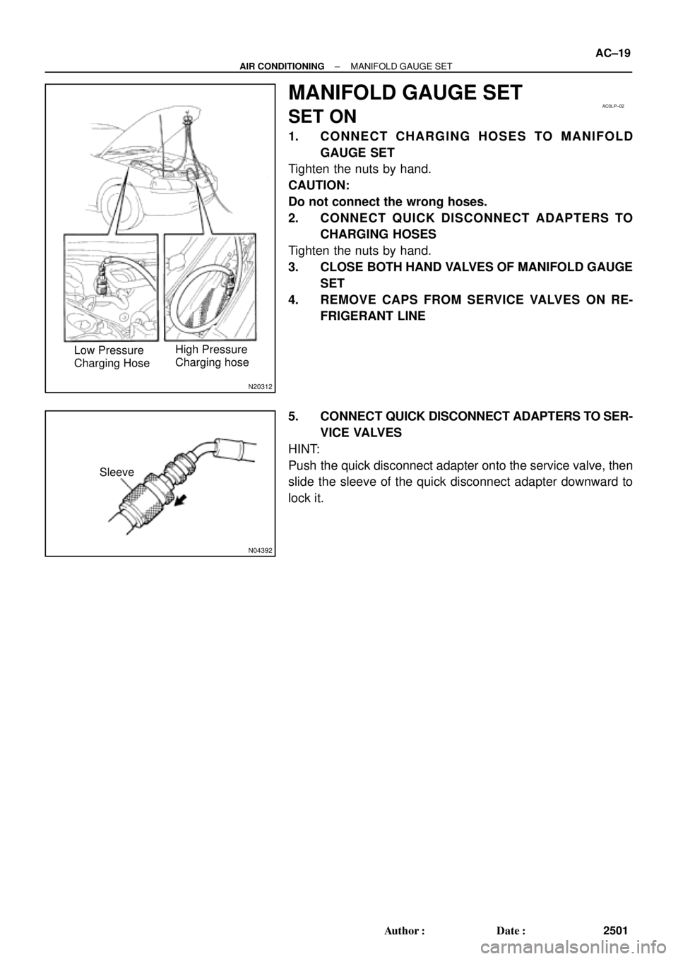
MANIFOLD GAUGE SET
SET ON
1. CONNECT CHARGING HOSES TO MANIFOLD
GAUGE SET
Tighten the nuts by hand.
CAUTION:
Do not connect the wrong hoses.
2. CONNECT QUICK DISCONNECT ADAPTERS TO
CHARGING HOSES
Tighten the nuts by hand.
3. CLOSE BOTH HAND VALVES OF MANIFOLD GAUGE
SET
4. REMOVE CAPS FROM SERVICE VALVES ON RE-
FRIGERANT LINE
5. CONNECT QUICK DISCONNECT ADAPTERS TO SER-
VICE VALVES
HINT:
Push the quick disconnect adapter onto the service valve, then
slide the sleeve of the quick disconnect adapter downward to
lock it.
Page 20 of 4592
AC0LQ±02
N06553
AC±20
± AIR CONDITIONINGMANIFOLD GAUGE SET
2502 Author�: Date�:
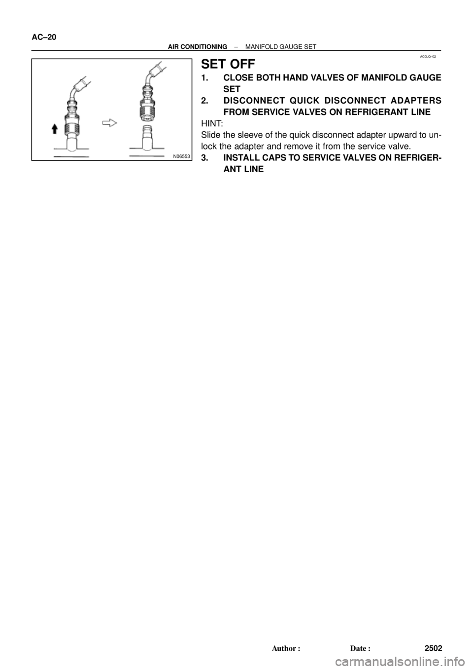
SET OFF
1. CLOSE BOTH HAND VALVES OF MANIFOLD GAUGE
SET
2. DISCONNECT QUICK DISCONNECT ADAPTERS
FROM SERVICE VALVES ON REFRIGERANT LINE
HINT:
Slide the sleeve of the quick disconnect adapter upward to un-
lock the adapter and remove it from the service valve.
3. INSTALL CAPS TO SERVICE VALVES ON REFRIGER-
ANT LINE
Page 153 of 4592
INTRODUCTIONHOW TO USE THIS MANUAL ±
IN±1
HOW TO USE THIS MANUAL
To assist you in finding your way through the manual, the Section Title and major heading are given
at the top of every page.
PREPARATION
Preparation lists the SST (Special Service Tools), recommended tools, equipment, lubricant and SSM
(Special Service Materials) which should be prepared before beginning the operation and explains the
purpose of each one.
REPAIR PROCEDURES
Most repair operations begin with an overview illustration. It identifies the components and shows how
the parts fit together.
Example:
IN002±0W
Page 157 of 4592

INTRODUCTIONGENERAL REPAIR INSTRUCTIONS ±
IN±5
the specified seal lock adhesive to the bolt, nut or
threads.
(c) Precoated parts are indicated in the component il-
lustrations by the º�º symbol.
7. When necessary, use a sealer on gaskets to prevent
leaks.
8. Carefully observe all specifications for bolt tightening
torques. Always use a torque wrench.
9. Use of special service tools (SST) and special service ma-
terials (SSM) may be required, depending on the nature
of the repair. Be sure to use SST and SSM where speci-
fied and follow the proper work procedure. A list of SST
and SSM can be found at the preparation of AX section.
10. When replacing fuses, be sure the new fuse has the cor-
rect amperage rating. DO NOT exceed the rating or use
one with a lower rating.
11. To pull apart electrical connectors, pull on the connector
itself, not the wires.
12. Care must be taken when jacking up and supporting the
vehicle. Be sure to lift and support the vehicle at the prop-
er locations.
(a) If the vehicle is to be jacked up only at the front or
rear end, be sure to block the wheels at the opposite
end in order to ensure safety.
(b) After the vehicle is jacked up, be sure to support it on
stands. It is extremely dangerous to do any work on
a vehicle raised on a jack alone, even for a small job
that can be finished quickly.