Page 176 of 4592
AUTOMATIC TRANSAXLEOPERATION ±
AX±6
2. HYDRAULIC CONTROL SYSTEM
The hydraulic control system is composed of the oil pump, the valve body, the solenoid valves, the accu-
mulators, the clutches and brakes, and the governor valve as well as the fluid passages which connect
all of these components.
Based on the hydraulic pressure created by the oil pump, the hydraulic control system governs the hy-
draulic pressure acting on the torque converter clutch, clutches and brakes in accordance with the ve-
hicle driving conditions.
There are three solenoid valves on the valve body.
The No.1 and No.2 solenoid valves are turned on and off by signals from the ECM to operate the shift
valves and change the gear shift position.
The No.3 solenoid valve is operated by signals from the ECM to engage or disengage the lock±up
clutch of the torque converter.
Page 311 of 4592
AUTOMATIC TRANSAXLEOPERATION ±
AX±5
3. HYDRAULIC CONTROL SYSTEM
The hydraulic control system is composed of the oil pump, the valve body, the solenoid valves, the accu-
mulators, the clutches and brakes as well as the fluid passages which connect all of these components.
Based on the hydraulic pressure created by the oil pump, the hydraulic control system governs the hy-
draulic pressure acting on the torque converter clutch, clutches and brakes in accordance with the ve-
hicle driving conditions.
There are three solenoid valves on the valve body.
The No.1 and No.2 solenoid vales are turned on and off by signals from the ECM to operate the shift
valves and change the gear shift position.
The SL solenoid valve is operated by signals from the ECM to engage or disengage the lock±up clutch
of the torque converter clutch.
The SLN solenoid valve is operated by signals from the ECM to control the engagement speed and
reduce gear shift shock.
AX01A±0B
Page 454 of 4592
AUTOMATIC TRANSAXLEOPERATION ±
AX±5
3. HYDRAULIC CONTROL SYSTEM
The hydraulic control system is composed of the oil pump, the valve body, the solenoid valves, the accu-
mulators, the clutches and brakes as well as the fluid passages which connect all of these components.
Based on the hydraulic pressure created by the oil pump, the hydraulic control system governs the hy-
draulic pressure acting on the torque converter clutch, clutches and brakes in accordance with the ve-
hicle driving conditions.
There are three solenoid valves on the valve body.
The No.1 and No.2 solenoid vales are turned on and off by signals from the ECM to operate the shift
valves and change the gear shift position.
The SL solenoid valve is operated by signals from the ECM to engage or disengage the lock±up clutch
of the torque converter clutch.
The SLN solenoid valve is operated by signals from the ECM to control the engagement speed and
reduce gear shift shock.
AX01A±0B
Page 585 of 4592
1. Integration Relay (I/P J/B No.1)
2. Light Control Switch
3. Wire HarnessBE±1")
BE±4
± BODY ELECTRICALBODY ELECTRICAL SYSTEM
2224 Author�: Date�:
Taillight does not light.
(Headlight does not light)1. Integration Relay (I/P J/B No.1)
2. Light Control Switch
3. Wire HarnessBE±14
BE±24
±
Taillight does not light.
(Headlight is normal)
1. TAIL Fuse (I/P J/B No.1)
2. Taillight Control Relay (I/P J/B No.1)
3. Integration Relay (I/P J/B No.1)
4. Light Control Switch
5. Wire Harness±
BE±24
BE±14
BE±24
±
Only one side light does not light.1. Bulb
2. Wire Harness±
±
Rear Combination light does not light.
1. Bulb
2. Light Failure Sensor
3. Wire Harness±
BE±37
±
ºAuto Turn±off Systemº does not operate.
1. GAUGE Fuse (I/P J/B No.1)
2. Integration Relay (I/P J/B No.1)
3. Door Courtesy Switch (Driver's)
4. Wire Harness±
BE±14
BE±24
±
*Terminal L of generator and parking brake switch
TURN SIGNAL AND HAZARD WARNING SYSTEM
SymptomSuspect AreaSee page
ºHazardº and ºTurnº do not light up.
1. Hazard Warning Switch
2. Turn Signal Flasher
3. Wire HarnessBE±30
BE±30
±
The flashing frequency is abnormal.
1. Bulb
2. Turn Signal Switch
3. Wire Harness±
BE±30
±
Hazard warning light does not light up.
(Turn is normal.)1. HORN Fuse (E/G Room J/B No.2)
2. Wire Harness±
±
Hazard warning light does not light up in one direction.1. Hazard Warning Switch
2. Wire HarnessBE±30
±
*1Turn signal does not light up.
1. Ignition Switch
2. TURN Fuse (I/P J/B No.1)
3. Turn Signal Switch
4. Wire HarnessBE±14
±
BE±30
±
*2Turn signal does not light up.
1. TURN Fuse (I/P J/B No.1)
2. Turn Signal Switch
3. Wire Harness±
BE±30
±
Turn signal does not light up in one direction.1. Turn Signal Switch
2. Wire HarnessBE±30
±
Only one bulb does not light up.1. Bulb
2. Wire Harness±
±
*1: Combination meter, wiper and washer do not operate.
*
2: Combination meter, wiper and washer are normal.
INTERIOR LIGHT SYSTEM
SymptomSuspect AreaSee page
ºIlluminated Entry Systemº does not operate.
1. Door Courtesy Switch
2. Integration Relay (I/P J/B No.1)
3. Wire HarnessBE±32
BE±14
±
Only one interior light does not light up.1. Bulb
2. Wire Harness±
±
Interior light does not light up (All).1. DOME Fuse (E/G Room J/B No.2)
2. Wire Harness±
±
Page 588 of 4592

4. Wire Harness±")
± BODY ELECTRICALBODY ELECTRICAL SYSTEM
BE±7
2227 Author�: Date�:
Seat Belt warning light does not light up.
1. Bulb
2. Seat Belt Buckle Switch
3. Integration Relay (I/P J/B No.1)
4. Wire Harness±
BE±47
BE±47
±
Discharge warning light does not light up.
1. IGN Fuse (I/P J/B No.1)
2. Bulb
3. Wire Harness
4. Generator (5S±FE)
(1MZ±FE)±
±
±
CH±1
CH±1
Light Failure warning light does not light up.
1. Bulb
2. Light Failure Sensor
3. Bulb Check Relay
4. Wire Harness
5. Taillight system±
BE±37
BE±47
±
BE±24
Brake warning light does not light up.
1. Bulb
2. Parking Brake Switch
3. Brake Fluid Level Warning Switch
4. Bulb Check Relay
5. Meter Circuit Plate
6. Wire Harness±
BE±47
BE±47
BE±47
BE±46
±
SRS Warning light does not light up.
1. ECU±B Fuse (E/G Room J/B No.2)
2. Bulb
3. Airbag Sensor Assembly
4. Meter Circuit Plate
5. Wire Harness±
±
DI±626
BE±46
±
Open Door warning light does not light up.
1. DOME Fuse (E/G Room J/B No.2)
2. Bulb
3. Door Courtesy Switch
4. Meter Circuit Plate
5. Wire Harness±
±
BE±32
BE±46
±
Washer Level warning light does not light up.
1. Bulb
2. Washer Fluid Level Warning Switch
3. Meter Circuit Plate
4. Wire Harness±
BE±47
BE±46
±
COMBINATION METER
INDICATOR LIGHTS:
SymptomSuspect AreaSee page
O/D OFF indicator light does not light up.
1. Bulb
2. O/D OFF Switch (A140E)
(A541E)
3. Meter Circuit Plate
4. Wire Harness±
DI±431
DI±487
BE±46
±
Cruise Control indicator light does not light up.
1. Bulb
2. Cruise Control ECU
3. Meter Circuit Plate
4. Wire Harness±
IN±31
BE±46
±
High beam indicator light does not light up.
1. Bulb
2. Meter Circuit Plate
3. Wire Harness
4. Headlight System±
BE±46
±
BE±22
Turn indicator light does not light up.
1. Bulb
2. Meter Circuit Plate
3. Wire Harness
4. Turn Signal and Hazard Warning System±
BE±46
±
BE±29
Page 592 of 4592
BE0A0±03
Z19043
Engine Room Relay Block No.1
Engine Room Junction
Block No.2
Engine Room Relay Block No.2
Instrument Panel Junction Block No.1
Turn Signal Flasher
± BODY ELECTRICALPOWER SOURCE
BE±11
2231 Author�: Date�:
POWER SOURCE
LOCATION
Page 610 of 4592
BE0A8±03
Z19045
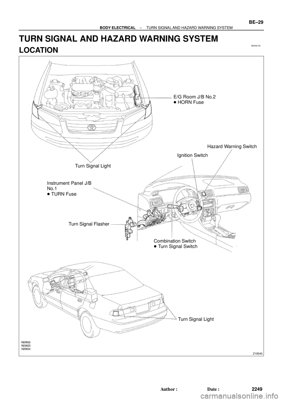
E/G Room J/B No.2
� HORN Fuse
Turn Signal Light
Instrument Panel J/B
No.1
� TURN Fuse
Turn Signal Flasher
Combination Switch
� Turn Signal SwitchIgnition SwitchHazard Warning Switch
Turn Signal Light
± BODY ELECTRICALTURN SIGNAL AND HAZARD WARNING SYSTEM
BE±29
2249 Author�: Date�:
TURN SIGNAL AND HAZARD WARNING SYSTEM
LOCATION
Page 611 of 4592

N20140
1 2 3
4
5 6 7 8 9 10
BE±30
± BODY ELECTRICALTURN SIGNAL AND HAZARD WARNING SYSTEM
2250 Author�: Date�:
INSPECTION
1")
BE0A9±02
N20150
Right
Left
2 31
BE1843
1 23
Turn Signal Light Bulbs (21 W)
N20140
1 2 3
4
5 6 7 8 9 10
BE±30
± BODY ELECTRICALTURN SIGNAL AND HAZARD WARNING SYSTEM
2250 Author�: Date�:
INSPECTION
1. INSPECT TURN SIGNAL SWITCH CONTINUITY
Switch positionTester connectionSpecified condition
Left turn1 ± 2Continuity
Neutral±No continuity
Right turn2 ± 3Continuity
If continuity is not as specified, replace the switch.
2. INSPECT TURN SIGNAL FLASHER OPERATION
(a) Connect the positive (+) lead from the battery to terminal
2 and the negative (±) lead to terminal 3.
(b) Connect the 2 turn signal light bulbs in parallel to each
other to terminals 1 and 3, check that the bulbs flash.
HINT:
The turn signal lights should flash 60 to 120 times per minute.
If one of the front or rear turn signal lights has an open circuit,
the number of flashes will be more than 140 per minute.
If operation is not as specified, replace the flasher.
3. INSPECT HAZARD WARNING SWITCH CONTINUITY
Switch positionTester connectionSpecified condition
Switch OFF7 ± 10Continuity
Switch ON5 ± 6 ± 9
7 ± 8Continuity
Illumination circuit2 ± 3Continuity
If continuity is not as specified, replace the switch.