Page 2 of 4592
AC±2
± AIR CONDITIONINGAIR CONDITIONING SYSTEM
2484 Author�: Date�:
9. SUPPLEMENTAL RESTRAINT SYSTEM (SRS)
The CAMRY is equipped with an SRS (Supplemental Restraint
System) such as the driver airbag and passenger airbag. Fail-
ure to carry out service operations the correct sequence could
cause the SRS to unexpectedly deployed during servicing, pos-
sible the SRS may fail to operate when required. Before servic-
ing (including removal or installation of parts, inspection or re-
placement), be sure to read the following item carefully, then
follow the correct procedure described in the repair manual.
Page 28 of 4592
I03838
SST
I03839
PushSST
Pull
SST
Release
Lever
I06919
Disconnect the tube
using hand
Screw
Driver
Tube
I06878
Correct Wrong
Gap
N20281
AC±28
± AIR CONDITIONINGAIR CONDITIONING UNIT
2510 Author�: Date�:
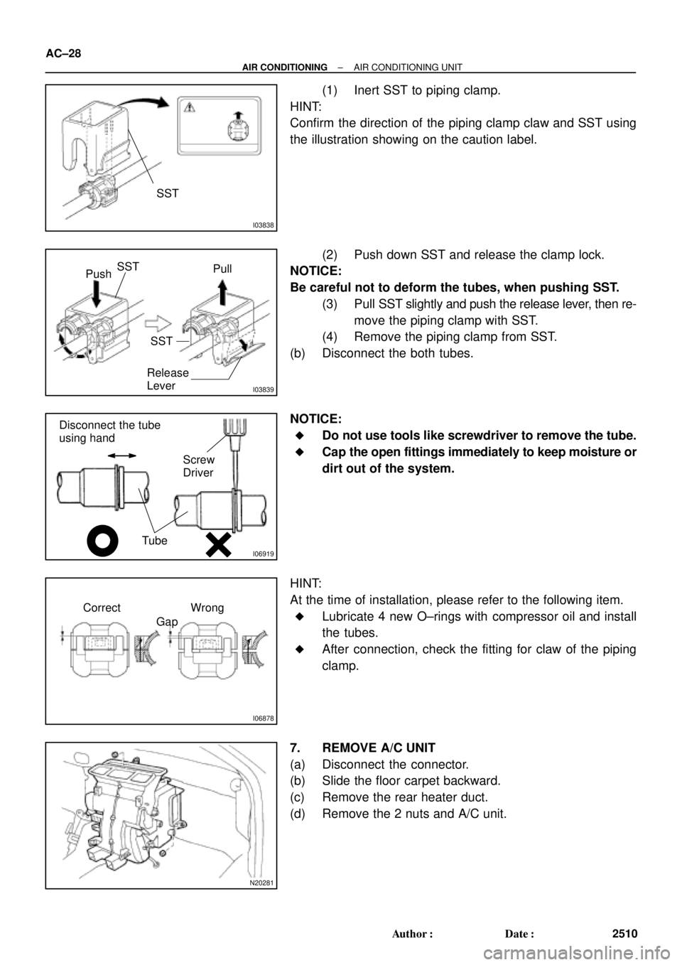
(1) Inert SST to piping clamp.
HINT:
Confirm the direction of the piping clamp claw and SST using
the illustration showing on the caution label.
(2) Push down SST and release the clamp lock.
NOTICE:
Be careful not to deform the tubes, when pushing SST.
(3) Pull SST slightly and push the release lever, then re-
move the piping clamp with SST.
(4) Remove the piping clamp from SST.
(b) Disconnect the both tubes.
NOTICE:
�Do not use tools like screwdriver to remove the tube.
�Cap the open fittings immediately to keep moisture or
dirt out of the system.
HINT:
At the time of installation, please refer to the following item.
�Lubricate 4 new O±rings with compressor oil and install
the tubes.
�After connection, check the fitting for claw of the piping
clamp.
7. REMOVE A/C UNIT
(a) Disconnect the connector.
(b) Slide the floor carpet backward.
(c) Remove the rear heater duct.
(d) Remove the 2 nuts and A/C unit.
Page 53 of 4592
AC0MD±01
AC±52
± AIR CONDITIONINGCONDENSER
2534 Author�: Date�:
CONDENSER
ON±VEHICLE INSPECTION
1. INSPECT CONDENSER FINS FOR BLOCKAGE OR DAMAGE
�If the fins are clogged, wash them with water and dry with compressed air.
NOTICE:
Be careful not to damage the fins.
�If the fins are bent, straighten them with a screwdriver or pliers.
2. INSPECT CONDENSER AND FITTINGS FOR LEAKAGE
Using a gas leak detector, check for leakage of refrigerant.
If there is leakage, check the tightening torque at the joints.
Page 84 of 4592
AC0NF±02
± AIR CONDITIONINGAIR CONDITIONING CONTROL ASSEMBLY
AC±83
2565 Author�: Date�:
DISASSEMBLY
1. REMOVE A/C SWITCH AND DEFOGGER SWITCH
Using a screwdriver, release the claw and pull out the switch backward.
HINT:
Tape the screwdriver tip before use.
2. REMOVE HEATER CONTROL KNOBS
3. REMOVE HEATER CONTROL CABLE
4. REMOVE BLOWER SPEED CONTROL SWITCH
Remove the 2 screws and pull out the switch.
5. REMOVE MODE SWITCH
Remove the 2 screws and pull out the switch.
6. REMOVE HEATER CONTROL NAME SHEET
(a) Remove the 2 screws.
(b) Using a screwdriver, release the 4 claws and heater control name sheet.
HINT:
Tape the screwdriver tip before use.
Page 100 of 4592
Z10941 AT0493
AT7868
AT0399
OR0038
Z19291
16 (0.63)
Shift Solenoid
Valve No.1
16 (0.63)Shift Solenoid
Valve No.2
AT3008
mm (in.) AX±6
± AUTOMATIC TRANSAXLE (A140E)VALVE BODY ASSEMBLY
1899 Author�: Date�:
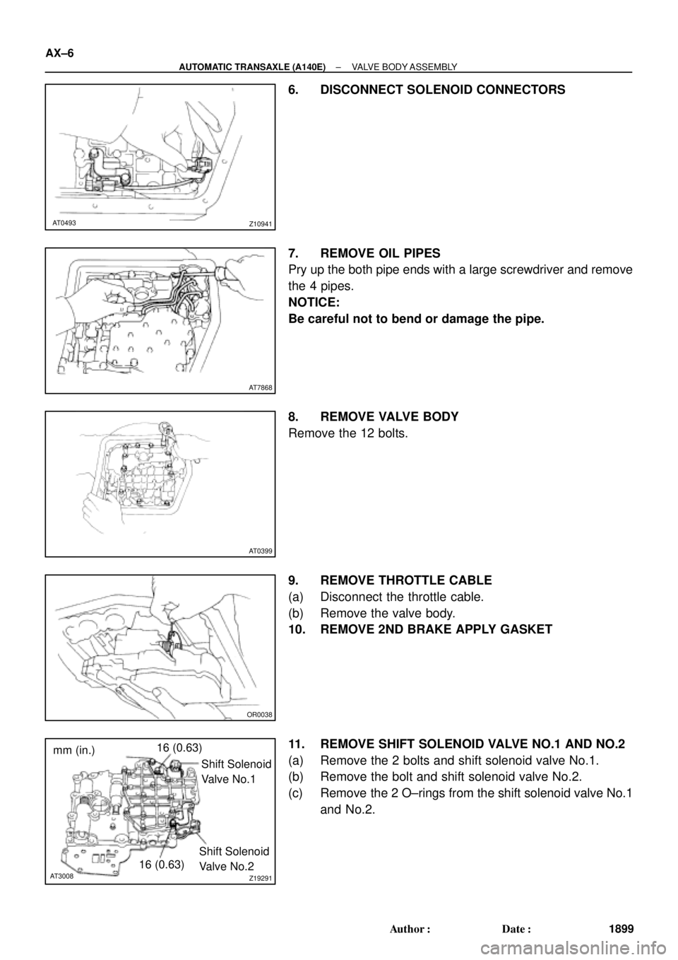
6. DISCONNECT SOLENOID CONNECTORS
7. REMOVE OIL PIPES
Pry up the both pipe ends with a large screwdriver and remove
the 4 pipes.
NOTICE:
Be careful not to bend or damage the pipe.
8. REMOVE VALVE BODY
Remove the 12 bolts.
9. REMOVE THROTTLE CABLE
(a) Disconnect the throttle cable.
(b) Remove the valve body.
10. REMOVE 2ND BRAKE APPLY GASKET
11. REMOVE SHIFT SOLENOID VALVE NO.1 AND NO.2
(a) Remove the 2 bolts and shift solenoid valve No.1.
(b) Remove the bolt and shift solenoid valve No.2.
(c) Remove the 2 O±rings from the shift solenoid valve No.1
and No.2.
Page 126 of 4592
AX03P±01
Q00229
Q06496
Q05727
Q04617
± AUTOMATIC TRANSAXLE (A541E)PARK/NEUTRAL POSITION (PNP) SWITCH
AX±5
1925 Author�: Date�:
PARK/NEUTRAL POSITION (PNP)
SWITCH
ON±VEHICLE REPAIR
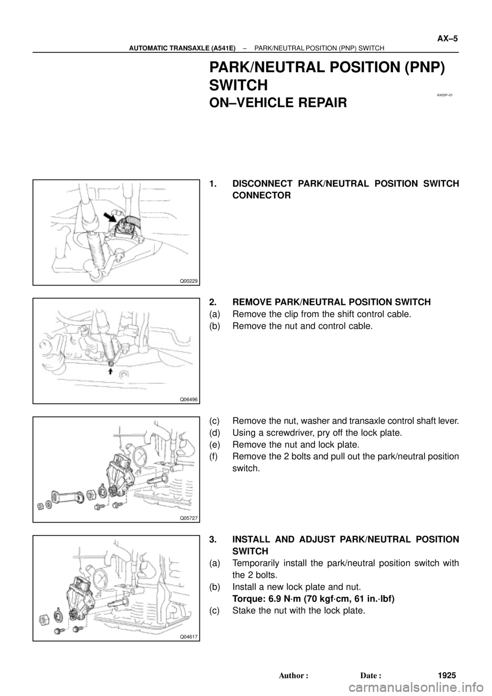
1. DISCONNECT PARK/NEUTRAL POSITION SWITCH
CONNECTOR
2. REMOVE PARK/NEUTRAL POSITION SWITCH
(a) Remove the clip from the shift control cable.
(b) Remove the nut and control cable.
(c) Remove the nut, washer and transaxle control shaft lever.
(d) Using a screwdriver, pry off the lock plate.
(e) Remove the nut and lock plate.
(f) Remove the 2 bolts and pull out the park/neutral position
switch.
3. INSTALL AND ADJUST PARK/NEUTRAL POSITION
SWITCH
(a) Temporarily install the park/neutral position switch with
the 2 bolts.
(b) Install a new lock plate and nut.
Torque: 6.9 N´m (70 kgf´cm, 61 in.´lbf)
(c) Stake the nut with the lock plate.
Page 128 of 4592
AX03Q±02
AT3785
AT0103
D01019
Q05728
Connector
± AUTOMATIC TRANSAXLE (A541E)VALVE BODY ASSEMBLY
AX±7
1927 Author�: Date�:
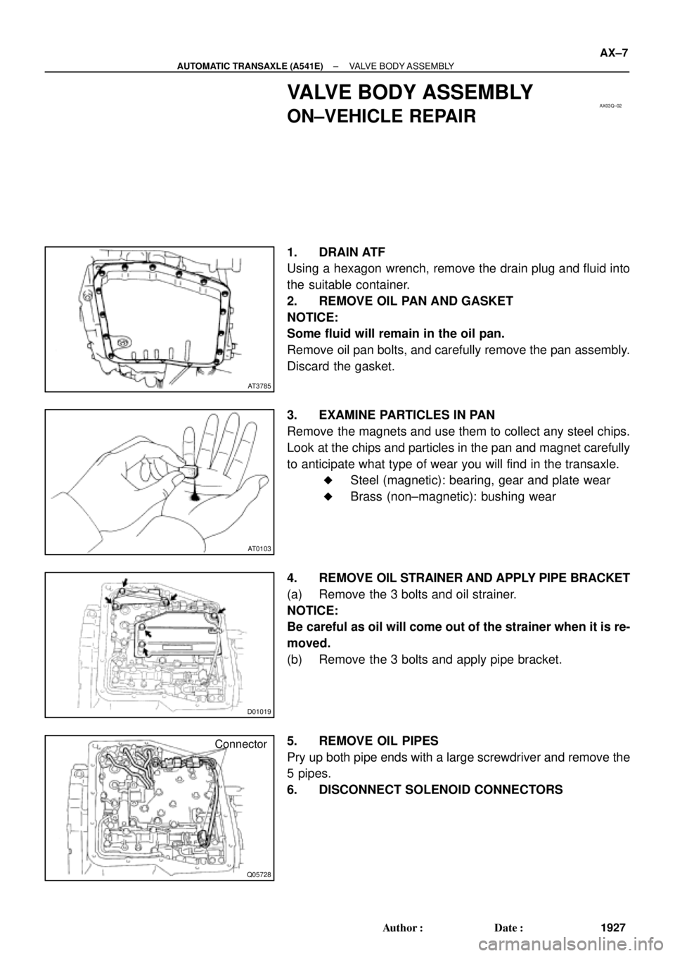
VALVE BODY ASSEMBLY
ON±VEHICLE REPAIR
1. DRAIN ATF
Using a hexagon wrench, remove the drain plug and fluid into
the suitable container.
2. REMOVE OIL PAN AND GASKET
NOTICE:
Some fluid will remain in the oil pan.
Remove oil pan bolts, and carefully remove the pan assembly.
Discard the gasket.
3. EXAMINE PARTICLES IN PAN
Remove the magnets and use them to collect any steel chips.
Look at the chips and particles in the pan and magnet carefully
to anticipate what type of wear you will find in the transaxle.
�Steel (magnetic): bearing, gear and plate wear
�Brass (non±magnetic): bushing wear
4. REMOVE OIL STRAINER AND APPLY PIPE BRACKET
(a) Remove the 3 bolts and oil strainer.
NOTICE:
Be careful as oil will come out of the strainer when it is re-
moved.
(b) Remove the 3 bolts and apply pipe bracket.
5. REMOVE OIL PIPES
Pry up both pipe ends with a large screwdriver and remove the
5 pipes.
6. DISCONNECT SOLENOID CONNECTORS
Page 129 of 4592
D01020
D01021
D01059
D01058
D01023
AX±8
± AUTOMATIC TRANSAXLE (A541E)VALVE BODY ASSEMBLY
1928 Author�: Date�:
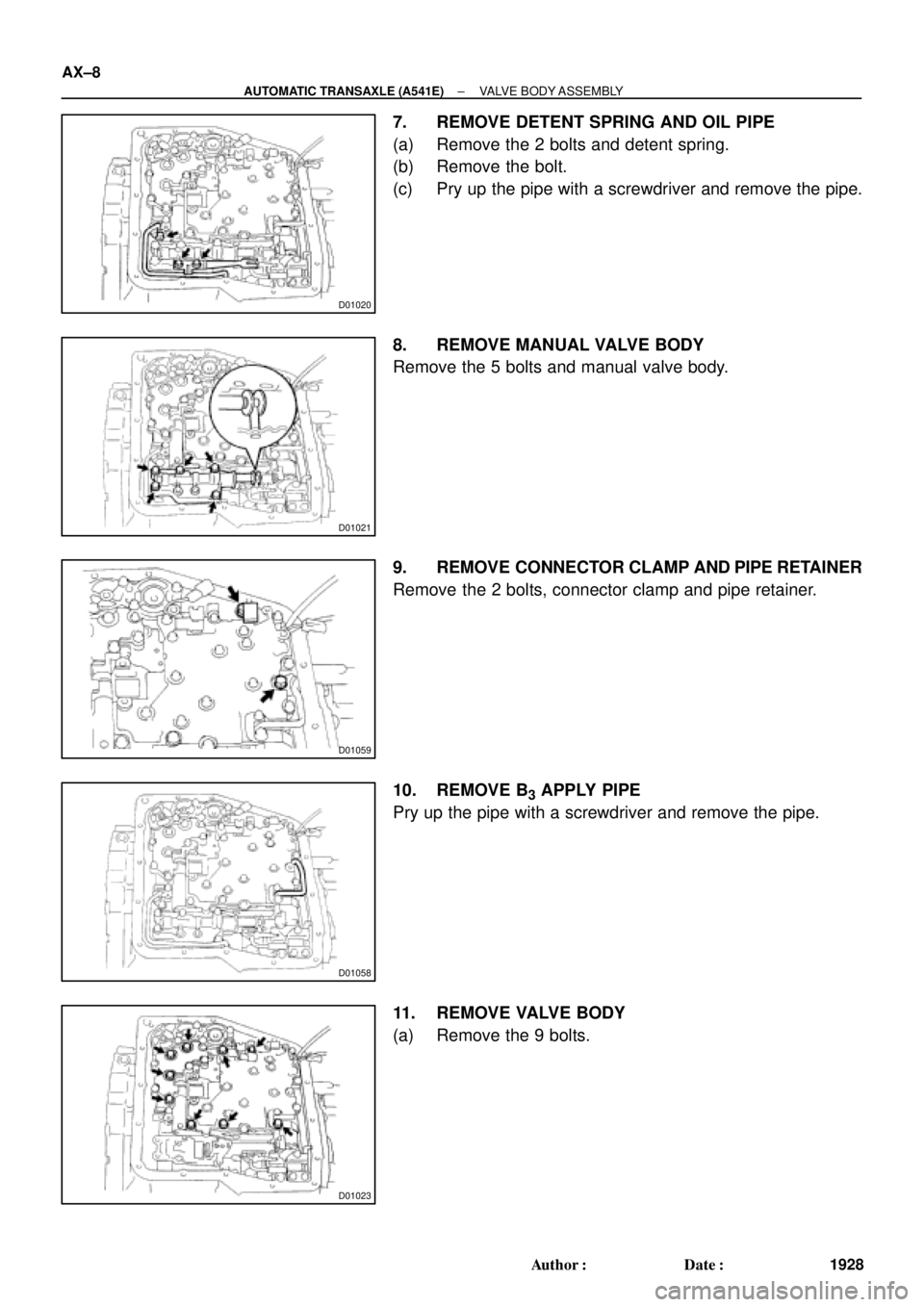
7. REMOVE DETENT SPRING AND OIL PIPE
(a) Remove the 2 bolts and detent spring.
(b) Remove the bolt.
(c) Pry up the pipe with a screwdriver and remove the pipe.
8. REMOVE MANUAL VALVE BODY
Remove the 5 bolts and manual valve body.
9. REMOVE CONNECTOR CLAMP AND PIPE RETAINER
Remove the 2 bolts, connector clamp and pipe retainer.
10. REMOVE B
3 APPLY PIPE
Pry up the pipe with a screwdriver and remove the pipe.
11. REMOVE VALVE BODY
(a) Remove the 9 bolts.