Page 130 of 4592
OR0038
Q05643
Q05657
Q05402
Q05657
± AUTOMATIC TRANSAXLE (A541E)VALVE BODY ASSEMBLY
AX±9
1929 Author�: Date�:
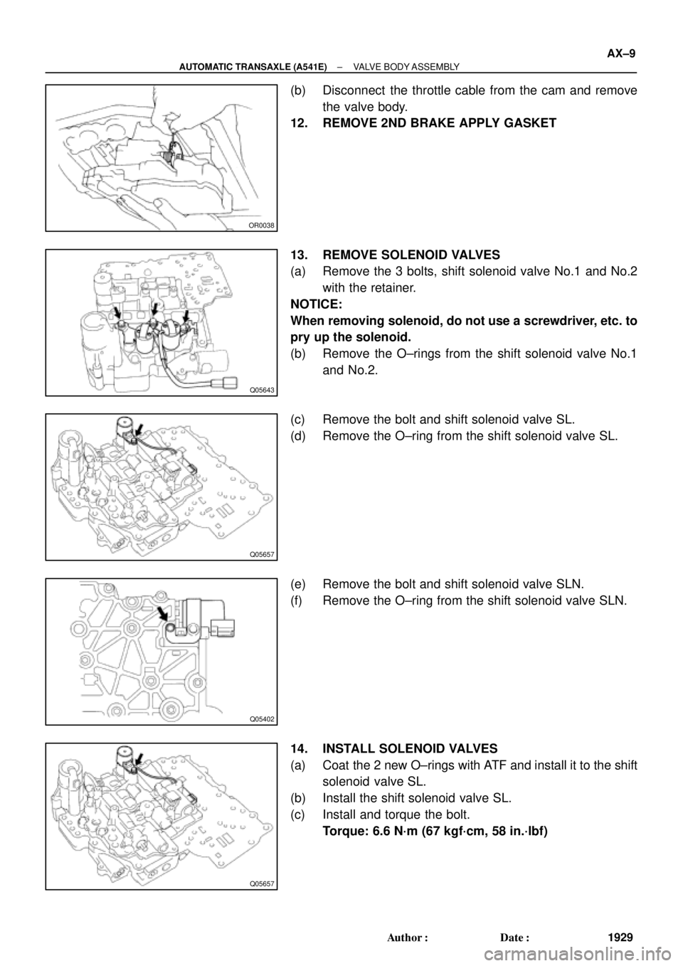
(b) Disconnect the throttle cable from the cam and remove
the valve body.
12. REMOVE 2ND BRAKE APPLY GASKET
13. REMOVE SOLENOID VALVES
(a) Remove the 3 bolts, shift solenoid valve No.1 and No.2
with the retainer.
NOTICE:
When removing solenoid, do not use a screwdriver, etc. to
pry up the solenoid.
(b) Remove the O±rings from the shift solenoid valve No.1
and No.2.
(c) Remove the bolt and shift solenoid valve SL.
(d) Remove the O±ring from the shift solenoid valve SL.
(e) Remove the bolt and shift solenoid valve SLN.
(f) Remove the O±ring from the shift solenoid valve SLN.
14. INSTALL SOLENOID VALVES
(a) Coat the 2 new O±rings with ATF and install it to the shift
solenoid valve SL.
(b) Install the shift solenoid valve SL.
(c) Install and torque the bolt.
Torque: 6.6 N´m (67 kgf´cm, 58 in.´lbf)
Page 187 of 4592
AUTOMATIC TRANSAXLECOMPONENT PARTS REMOVAL ±
AX±17
11. REMOVE OIL TUBES
Pry up both tube ends with a large screwdriver and re-
move the 4 tubes.
12. REMOVE MANUAL DETENT SPRING
13. REMOVE MANUAL VALVE AND MANUAL VALVE
BODY
14. REMOVE VALVE BODY
(a) Remove the 12 bolts.
15. REMOVE THROTTLE CABLE AND SOLENOID WIR-
ING FROM CASE
16. REMOVE SECOND BRAKE APPLY GASKET
Page 190 of 4592
AUTOMATIC TRANSAXLECOMPONENT PARTS REMOVAL ±
AX±20
22. REMOVE DIRECT CLUTCH FROM OIL PUMP
23. BE CAREFUL WHEN REMOVING RACE BEHIND OIL
PUMP
24. REMOVE CLUTCH DRUM THRUST WASHER
25. REMOVE FORWARD CLUTCH
26. REMOVE BEARINGS AND RACES FROM FORWARD
CLUTCH
27. REMOVE SECOND COAST BRAKE BAND
(a) Push the pin with a small screwdriver and remove it from
the bolt hole of the oil pump mounting.
(b) Remove the brake band.
28. REMOVE FRONT PLANETARY RING GEAR
Page 197 of 4592
AUTOMATIC TRANSAXLECOMPONENT PARTS REMOVAL ±
AX±27
55. REMOVE PIN, SPRING AND PARKING LOCK PAWL
56. REMOVE MANUAL VALVE SHAFT
(a) Remove the retaining spring.
(b) Using a hammer and chisel, pry and turn the collar.
(c) Using a hammer and punch, drive out the pin.
(d) Slide out the shaft and remove the manual valve lever
from the case.
57. REMOVE MANUAL SHAFT OIL SEAL
Remove the oil seal with a screwdriver.
Page 199 of 4592
AUTOMATIC TRANSAXLECOMPONENT PARTS REMOVAL ±
AX±29
6. REMOVE DIFFERENTIAL CASE, OUTER RACE AND
ADJUSTING SHIM
Remove the differential case, the outer race and the ad-
justing shim from the case.
7. MEASURE DRIVE PINION PRELOAD
Using a torque meter, measure the drive pinion preload.
Preload (at starting):
Reused bearing
0.5 ± 0.8 N´m (5 ± 8 kgf´cm, 4.3 ± 6.9 in.´lbf)
The total preload measured in step 2 minus the drive pin-
ion preload equals 0.1 ± 0.2 N´m (1.5 ± 2.0 kgf´cm, 1.3 ±
1.7in.´lbf).
If the result is not within this specification, the side bearing
preload is bad.
8. REMOVE DRIVE PINION CAP
(a) Remove the drive pinion cap installation bolt.
(b) Using a screwdriver, push out the drive pinion cap.
9. REMOVE COUNTER DRIVEN GEAR
(a) Using a chisel, loosen the staked part of the nut.
Page 207 of 4592

AUTOMATIC TRANSAXLEOIL PUMP ±
AX±37
3. REMOVE STATOR SHAFT
Remove the 11 bolts and stator shaft.
Keep the gears in assembly order.
4. REMOVE FRONT OIL SEAL
Pry off the oil seal with a screwdriver.
OIL PUMP BUSHING INSPECTION
1. CHECK BODY CLEARANCE OF DRIVEN GEAR
Push the driven gear to one side of the body.
Using a feeler gauge, measure the clearance.
Standard body clearance:
0.07 ± 0.15 mm (0.0028 ± 0.0059 in.)
Maximum body clearance:
0.3 mm (0.012 in.)
If the body clearance is greater than the maximum, re-
place the oil pump body subassembly.
2. CHECK TIP CLEARANCE OF DRIVEN GEAR
Measure between the driven gear teeth and the cres-
cent±shaped part of the pump body.
Standard tip clearance:
0.11 ± 0.14 mm (0.0043 ± 0.0055 in.)
Maximum tip clearance:
0.3 mm (0.012 in.)
If the tip clearance is greater than the maximum, replace
the oil pump body subassembly.
3. CHECK SIDE CLEARANCE OF BOTH GEARS
Using a steel straightedge and a feeler gauge, measure
the side clearance of both gears.
Standard side clearance:
0.02 ± 0.05 mm (0.0008 ± 0.0020 in.)
Maximum side clearance:
0.1 mm (0.004 in.)
There are 3 different thicknesses for drive and driven
gears.
AX0F5±02
Page 209 of 4592
AUTOMATIC TRANSAXLEOIL PUMP ±
AX±39
3. INSTALL STATOR SHAFT ONTO PUMP BODY
Align the stator shaft with each bolt hole.
4. TIGHTEN 11 STATOR SHAFT BOLTS
Torque: 10 N´m (100 kgf´cm, 7 ft´lbf)
5. INSTALL THRUST WASHER
(a) Coat the thrust washer with petroleum jelly.
(b) Align the tab of the washer with the hollow of the pump
body.
6. INSTALL 2 OIL SEAL RINGS ON OIL PUMP
Install 2 oil seal rings to the stator shaft groove, then snug
them down by squeezing their ends together.
NOTICE: Do not spread the ring ends too much.
HINT: After installing the oil seal rings, check that they
move smoothly.
7. CHECK PUMP DRIVE GEAR ROTATION
Turn the drive gear with screwdrivers and make sure that
it rotates smoothly.
NOTICE: Be careful not to damage the oil seal lip.
Page 221 of 4592
AUTOMATIC TRANSAXLEFRONT PLANETARY GEAR ±
AX±51
4. INSTALL ONE±WAY CLUTCH AND SECOND BRAKE
HUB ON SUN GEAR
While turning the hub clockwise, slide the one±way clutch
onto the sun gear.
5. RECHECK OPERATION OF ONE±WAY CLUTCH
PLANETARY RING GEAR INSPECTION
1. INSPECT RING GEAR FLANGE BUSHING
Using a dial indicator, measure the inside diameter of the
flange bushing.
Standard inside diameter:
19.025 ± 19.050 mm (0.7490 ± 0.7500 in.)
If the inside diameter is greater than the maximum, re-
place the flange.
2. REMOVE RING GEAR FLANGE
(a) Using a screwdriver, remove the snap ring.
(b) Remove the flange from the ring gear.
3. INSTALL RING GEAR FLANGE
(a) Position the flange into the ring gear.
(b) Using a screwdriver, install the snap ring.
AX0FH±02