Page 1036 of 4592
BR0AP±03
F07213
R02874
BR±22
± BRAKEFRONT BRAKE PAD
2045 Author�: Date�:
REPLACEMENT
1. REMOVE FRONT WHEEL
Remove the wheel and temporarily fasten the disc with hub
nuts.
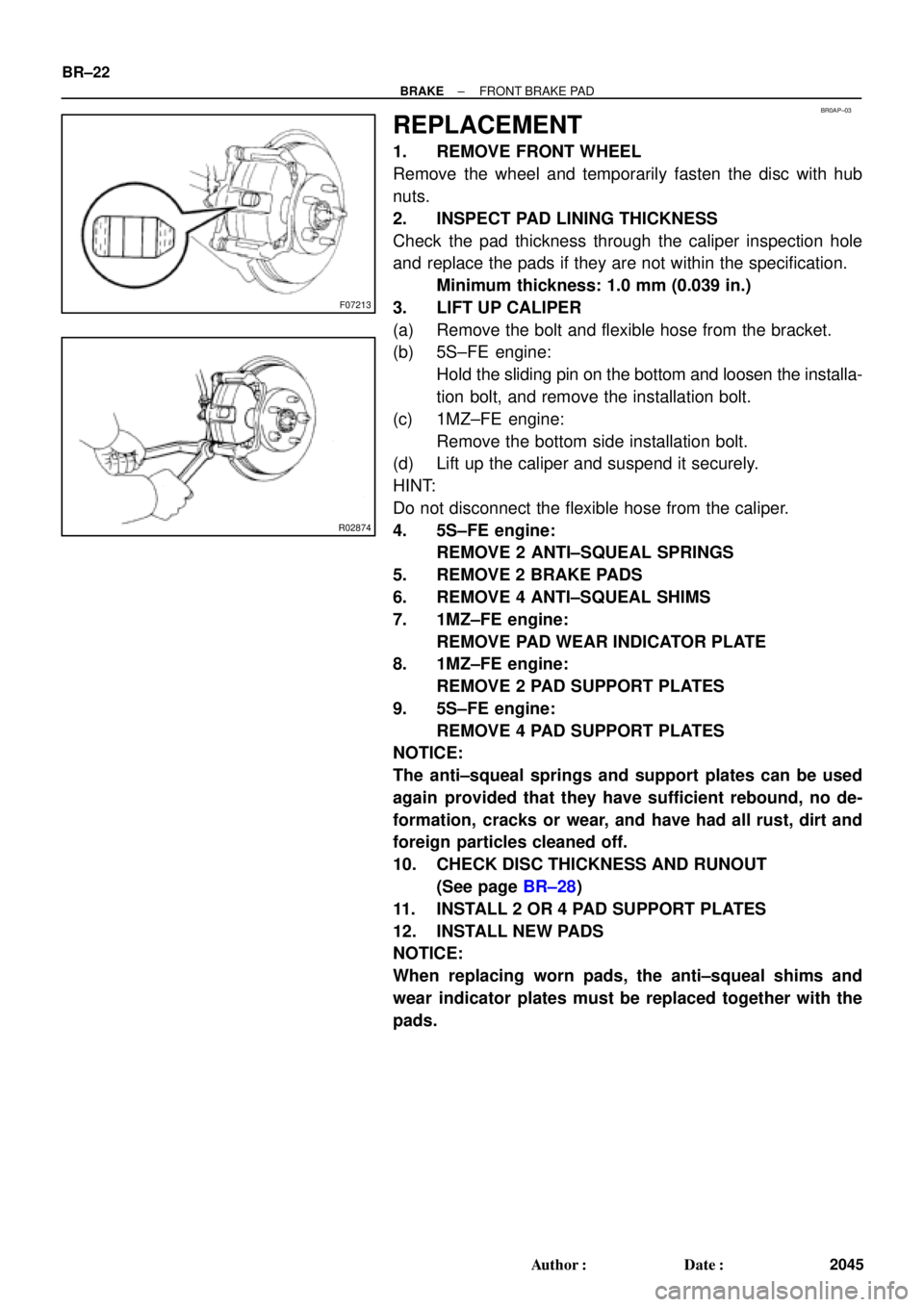
2. INSPECT PAD LINING THICKNESS
Check the pad thickness through the caliper inspection hole
and replace the pads if they are not within the specification.
Minimum thickness: 1.0 mm (0.039 in.)
3. LIFT UP CALIPER
(a) Remove the bolt and flexible hose from the bracket.
(b) 5S±FE engine:
Hold the sliding pin on the bottom and loosen the installa-
tion bolt, and remove the installation bolt.
(c) 1MZ±FE engine:
Remove the bottom side installation bolt.
(d) Lift up the caliper and suspend it securely.
HINT:
Do not disconnect the flexible hose from the caliper.
4. 5S±FE engine:
REMOVE 2 ANTI±SQUEAL SPRINGS
5. REMOVE 2 BRAKE PADS
6. REMOVE 4 ANTI±SQUEAL SHIMS
7. 1MZ±FE engine:
REMOVE PAD WEAR INDICATOR PLATE
8. 1MZ±FE engine:
REMOVE 2 PAD SUPPORT PLATES
9. 5S±FE engine:
REMOVE 4 PAD SUPPORT PLATES
NOTICE:
The anti±squeal springs and support plates can be used
again provided that they have sufficient rebound, no de-
formation, cracks or wear, and have had all rust, dirt and
foreign particles cleaned off.
10. CHECK DISC THICKNESS AND RUNOUT
(See page BR±28)
11. INSTALL 2 OR 4 PAD SUPPORT PLATES
12. INSTALL NEW PADS
NOTICE:
When replacing worn pads, the anti±squeal shims and
wear indicator plates must be replaced together with the
pads.
Page 1037 of 4592
R00595
R02981
± BRAKEFRONT BRAKE PAD
BR±23
2046 Author�: Date�:
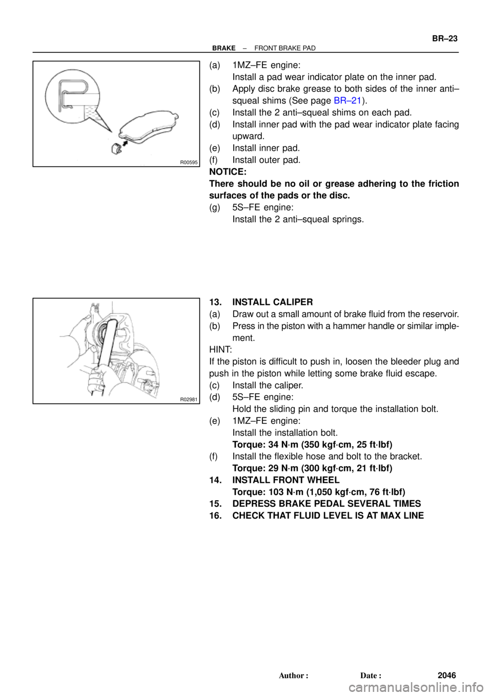
(a) 1MZ±FE engine:
Install a pad wear indicator plate on the inner pad.
(b) Apply disc brake grease to both sides of the inner anti±
squeal shims (See page BR±21).
(c) Install the 2 anti±squeal shims on each pad.
(d) Install inner pad with the pad wear indicator plate facing
upward.
(e) Install inner pad.
(f) Install outer pad.
NOTICE:
There should be no oil or grease adhering to the friction
surfaces of the pads or the disc.
(g) 5S±FE engine:
Install the 2 anti±squeal springs.
13. INSTALL CALIPER
(a) Draw out a small amount of brake fluid from the reservoir.
(b) Press in the piston with a hammer handle or similar imple-
ment.
HINT:
If the piston is difficult to push in, loosen the bleeder plug and
push in the piston while letting some brake fluid escape.
(c) Install the caliper.
(d) 5S±FE engine:
Hold the sliding pin and torque the installation bolt.
(e) 1MZ±FE engine:
Install the installation bolt.
Torque: 34 N´m (350 kgf´cm, 25 ft´lbf)
(f) Install the flexible hose and bolt to the bracket.
Torque: 29 N´m (300 kgf´cm, 21 ft´lbf)
14. INSTALL FRONT WHEEL
Torque: 103 N´m (1,050 kgf´cm, 76 ft´lbf)
15. DEPRESS BRAKE PEDAL SEVERAL TIMES
16. CHECK THAT FLUID LEVEL IS AT MAX LINE
Page 1040 of 4592
BR0AR±03
R02840
BR±26
± BRAKEFRONT BRAKE CALIPER
2049 Author�: Date�:
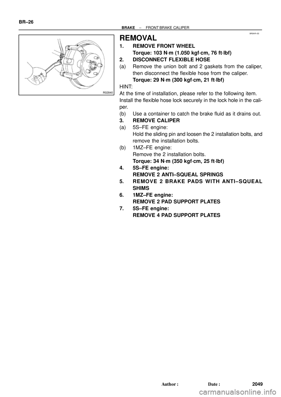
REMOVAL
1. REMOVE FRONT WHEEL
Torque: 103 N´m (1.050 kgf´cm, 76 ft´lbf)
2. DISCONNECT FLEXIBLE HOSE
(a) Remove the union bolt and 2 gaskets from the caliper,
then disconnect the flexible hose from the caliper.
Torque: 29 N´m (300 kgf´cm, 21 ft´lbf)
HINT:
At the time of installation, please refer to the following item.
Install the flexible hose lock securely in the lock hole in the cali-
per.
(b) Use a container to catch the brake fluid as it drains out.
3. REMOVE CALIPER
(a) 5S±FE engine:
Hold the sliding pin and loosen the 2 installation bolts, and
remove the installation bolts.
(b) 1MZ±FE engine:
Remove the 2 installation bolts.
Torque: 34 N´m (350 kgf´cm, 25 ft´lbf)
4. 5S±FE engine:
REMOVE 2 ANTI±SQUEAL SPRINGS
5. REMOVE 2 BRAKE PADS WITH ANTI±SQUEAL
SHIMS
6. 1MZ±FE engine:
REMOVE 2 PAD SUPPORT PLATES
7. 5S±FE engine:
REMOVE 4 PAD SUPPORT PLATES
Page 1051 of 4592
BR0B1±03
R00591
R00514
R10387
± BRAKEREAR BRAKE PAD
BR±37
2060 Author�: Date�:
REPLACEMENT
1. REMOVE REAR WHEEL
Remove the wheel and temporarily fasten the disc with the hub
nuts.
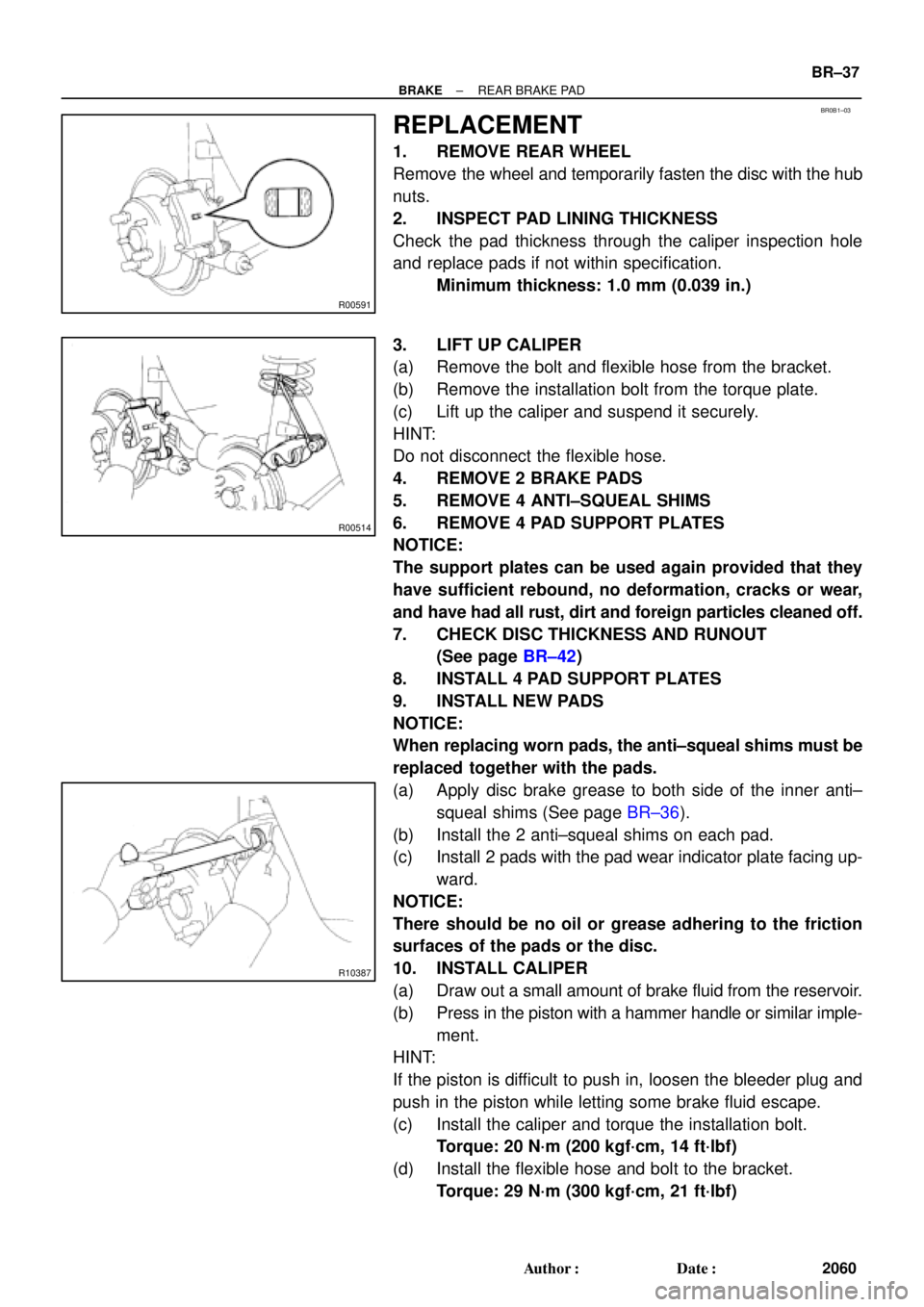
2. INSPECT PAD LINING THICKNESS
Check the pad thickness through the caliper inspection hole
and replace pads if not within specification.
Minimum thickness: 1.0 mm (0.039 in.)
3. LIFT UP CALIPER
(a) Remove the bolt and flexible hose from the bracket.
(b) Remove the installation bolt from the torque plate.
(c) Lift up the caliper and suspend it securely.
HINT:
Do not disconnect the flexible hose.
4. REMOVE 2 BRAKE PADS
5. REMOVE 4 ANTI±SQUEAL SHIMS
6. REMOVE 4 PAD SUPPORT PLATES
NOTICE:
The support plates can be used again provided that they
have sufficient rebound, no deformation, cracks or wear,
and have had all rust, dirt and foreign particles cleaned off.
7. CHECK DISC THICKNESS AND RUNOUT
(See page BR±42)
8. INSTALL 4 PAD SUPPORT PLATES
9. INSTALL NEW PADS
NOTICE:
When replacing worn pads, the anti±squeal shims must be
replaced together with the pads.
(a) Apply disc brake grease to both side of the inner anti±
squeal shims (See page BR±36).
(b) Install the 2 anti±squeal shims on each pad.
(c) Install 2 pads with the pad wear indicator plate facing up-
ward.
NOTICE:
There should be no oil or grease adhering to the friction
surfaces of the pads or the disc.
10. INSTALL CALIPER
(a) Draw out a small amount of brake fluid from the reservoir.
(b) Press in the piston with a hammer handle or similar imple-
ment.
HINT:
If the piston is difficult to push in, loosen the bleeder plug and
push in the piston while letting some brake fluid escape.
(c) Install the caliper and torque the installation bolt.
Torque: 20 N´m (200 kgf´cm, 14 ft´lbf)
(d) Install the flexible hose and bolt to the bracket.
Torque: 29 N´m (300 kgf´cm, 21 ft´lbf)
Page 1053 of 4592
BR0B2±03
W03262
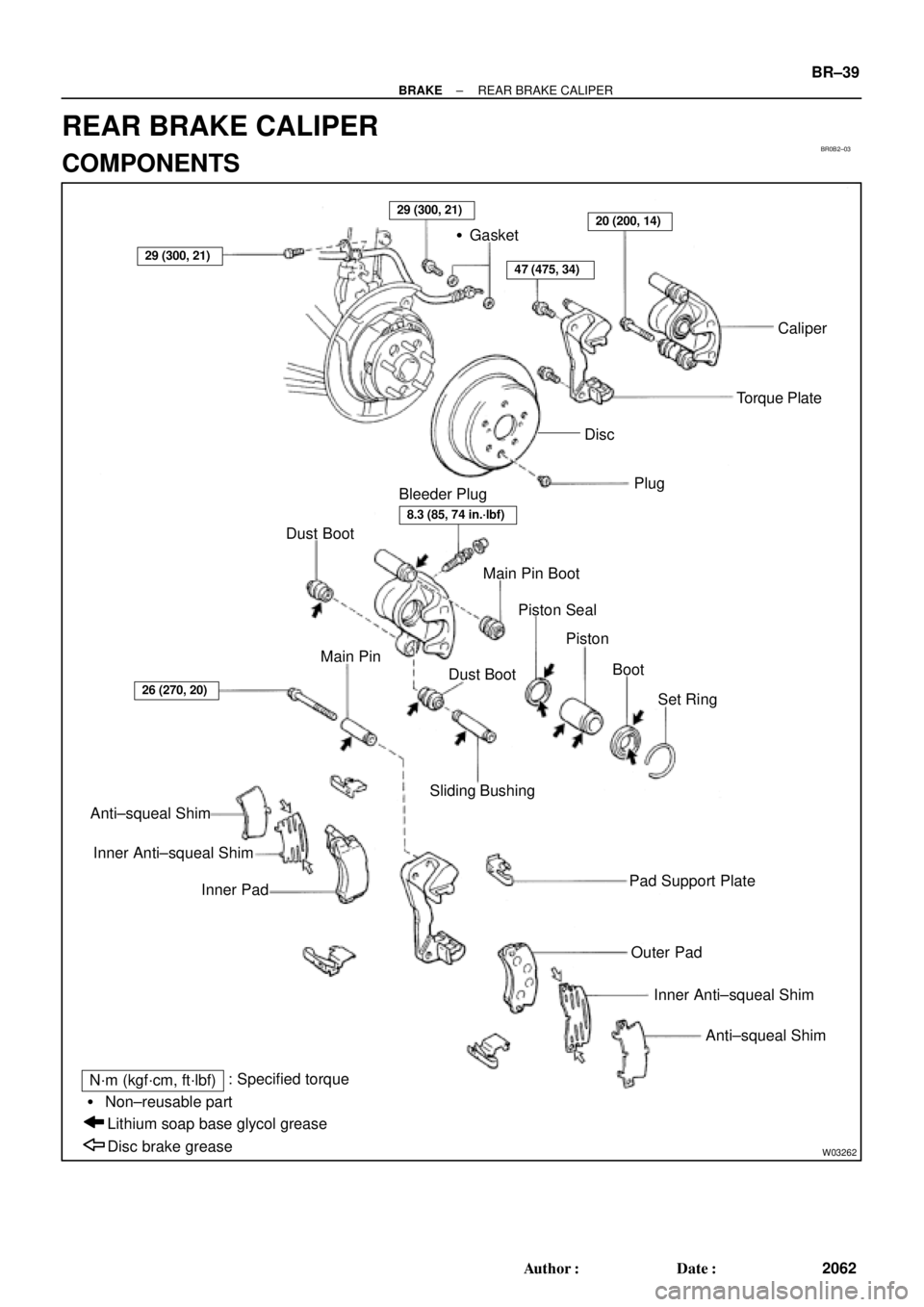
�Gasket
Caliper
Torque Plate
Plug
Bleeder Plug
Dust Boot
Main Pin Boot
Piston Seal
Piston
Boot
Set Ring Dust Boot Main Pin
Anti±squeal Shim
Inner Anti±squeal Shim
Inner PadSliding Bushing
Pad Support Plate
Outer Pad
Inner Anti±squeal Shim
Anti±squeal Shim
Disc brake grease Lithium soap base glycol grease � Non±reusable part
N´m (kgf´cm, ft´lbf): Specified torque
47 (475, 34)
20 (200, 14)
26 (270, 20)
29 (300, 21)
29 (300, 21)
8.3 (85, 74 in.´lbf)
Disc
± BRAKEREAR BRAKE CALIPER
BR±39
2062 Author�: Date�:
REAR BRAKE CALIPER
COMPONENTS
Page 1054 of 4592

BR0B3±03
W03263
W03264
BR±40
± BRAKEREAR BRAKE CALIPER
2063 Author�: Date�:
REMOVAL
1. REMOVE REAR WHEEL
Torque: 103 N´m (1.050 kgf´cm, 76 ft´lbf)
2. DISCONNECT FLEXIBLE HOSE
(a) Remove the union bolt and 2 gaskets from the caliper,
then disconnect the flexible hose from the caliper.
Torque: 29 N´m (300 kgf´cm, 21 ft´lbf)
HINT:
At the time of installation, please refer to the following item.
Insert the flexible hose lock securely in the lock hole in the cali-
per.
(b) Use a container to catch the brake fluid as it drains out.
3. REMOVE CALIPER
(a) Remove the installation bolt.
Torque: 20 N´m (200 kgf´cm, 14 ft´lbf)
(b) Remove the caliper from the torque plate.
4. REMOVE 2 BRAKE PADS WITH 4 ANTI±SQUEAL
SHIMS
5. REMOVE 4 PAD SUPPORT PLATES
NOTICE:
At the time of installation, please refer to the following item.
There should be no oil or grease adhering to the friction
surfaces of the pads or disc.
6. REMOVE MAIN PIN
Loosen the main pin installation bolt and remove the main pin.
Torque: 26 N´m (270 kgf´cm, 20 ft´lbf)
Page 2929 of 4592
MA0055
MA00M±01
MA±6
± MAINTENANCEBRAKE
49 Author�: Date�:
BRAKE
INSPECTION
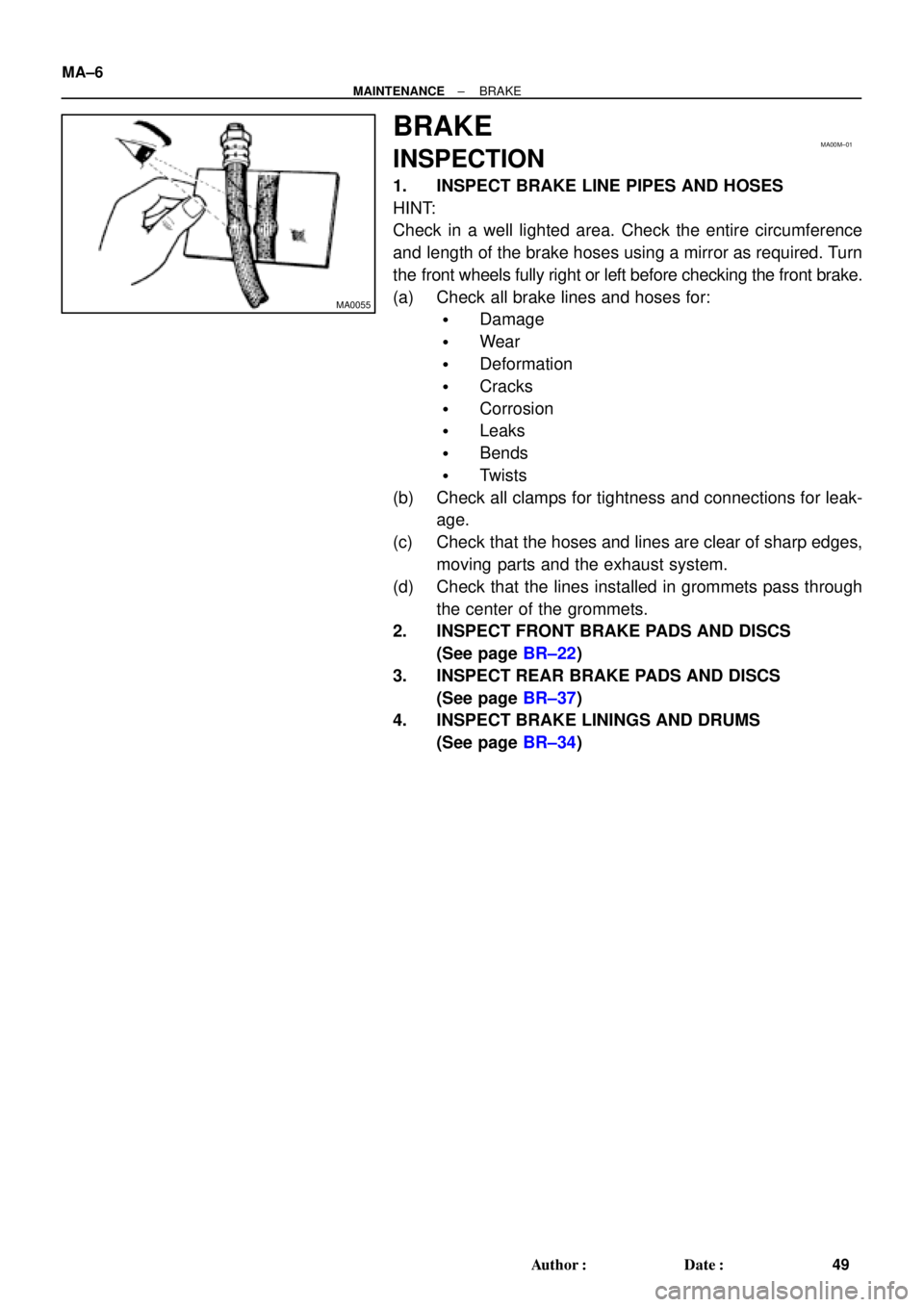
1. INSPECT BRAKE LINE PIPES AND HOSES
HINT:
Check in a well lighted area. Check the entire circumference
and length of the brake hoses using a mirror as required. Turn
the front wheels fully right or left before checking the front brake.
(a) Check all brake lines and hoses for:
�Damage
�Wear
�Deformation
�Cracks
�Corrosion
�Leaks
�Bends
�Twists
(b) Check all clamps for tightness and connections for leak-
age.
(c) Check that the hoses and lines are clear of sharp edges,
moving parts and the exhaust system.
(d) Check that the lines installed in grommets pass through
the center of the grommets.
2. INSPECT FRONT BRAKE PADS AND DISCS
(See page BR±22)
3. INSPECT REAR BRAKE PADS AND DISCS
(See page BR±37)
4. INSPECT BRAKE LININGS AND DRUMS
(See page BR±34)
Page 3755 of 4592

Toyota Supports ASE CertificationPage 1 of 1
BR001±99
Title:
FRONT BRAKE NOISE
Models:
'97±'99 V±6 Camry and '98±'99 Avalon
Technical Service
BULLETIN
April 23, 1999
New Front Brake Pad Kits are available to reduce front brake groan or grinding noise on
1997±1999 V6 Camry and 1998±1999 Avalon.
1997±1999 V6 Camrys built before VINs 4T1BF2 * K * XU078781 (NAP ± Plant 1)
4T1BF2 * K * XU930650 (NAP ± Plant 2)
JT2BF2 * K * X0179640 (TMC)
1998±1999 Avalons built before VIN 4T1BF18B * XU310454
PART NUMBERPART NAME
04465±33121Front Brake Pads
04945±33040Shim Kit (If Needed*)
* Visually inspect Shims for heat discoloration. If discolored, replace shims.
1. Surface the disc rotors with the ªOn±Car Brake Latheº to within serviceable limits.
2. If the rotors are unserviceable or below minimum thickness, replace the rotors.
3. Check any new disc rotors for runout.
4. If the disc rotor runout is over 0.03 mm (0.00012 in), perform a phase matching
procedure.
5. Replace the front brake pads.
6. Road test.
OP CODECOMBODESCRIPTIONTIMEOPNT1T2
Grind Front Discs and Replace Pads, Shims
(if needed) for Squeak (both sides)3699
473025AGrind Front Discs and Replace Pads, Shims
(if needed) for Vibration (both sides)2.104465±331212199
Grind Front Discs and Replace Pads, Shims
(if needed) for Groan/Grinding (both sides)9199
Applicable Warranty*:
This repair is covered under the Toyota Basic Warranty. This warranty is in effect for
36 months or 36,000 miles, whichever occurs first, from the vehicle's in±service date.
* Warranty application is limited to correction of a problem based upon a customer's specific complaint.
BRAKES
Introduction
Affected
Vehicles
Parts
Information
Repair
Procedure
Warranty
Information