Page 2823 of 4592

IN05Y±07
IN±20± INTRODUCTIONHOW TO TROUBLESHOOT ECU CONTROLLED
SYSTEMS
20 Author�: Date�:
HOW TO TROUBLESHOOT ECU CONTROLLED SYSTEMS
GENERAL INFORMATION
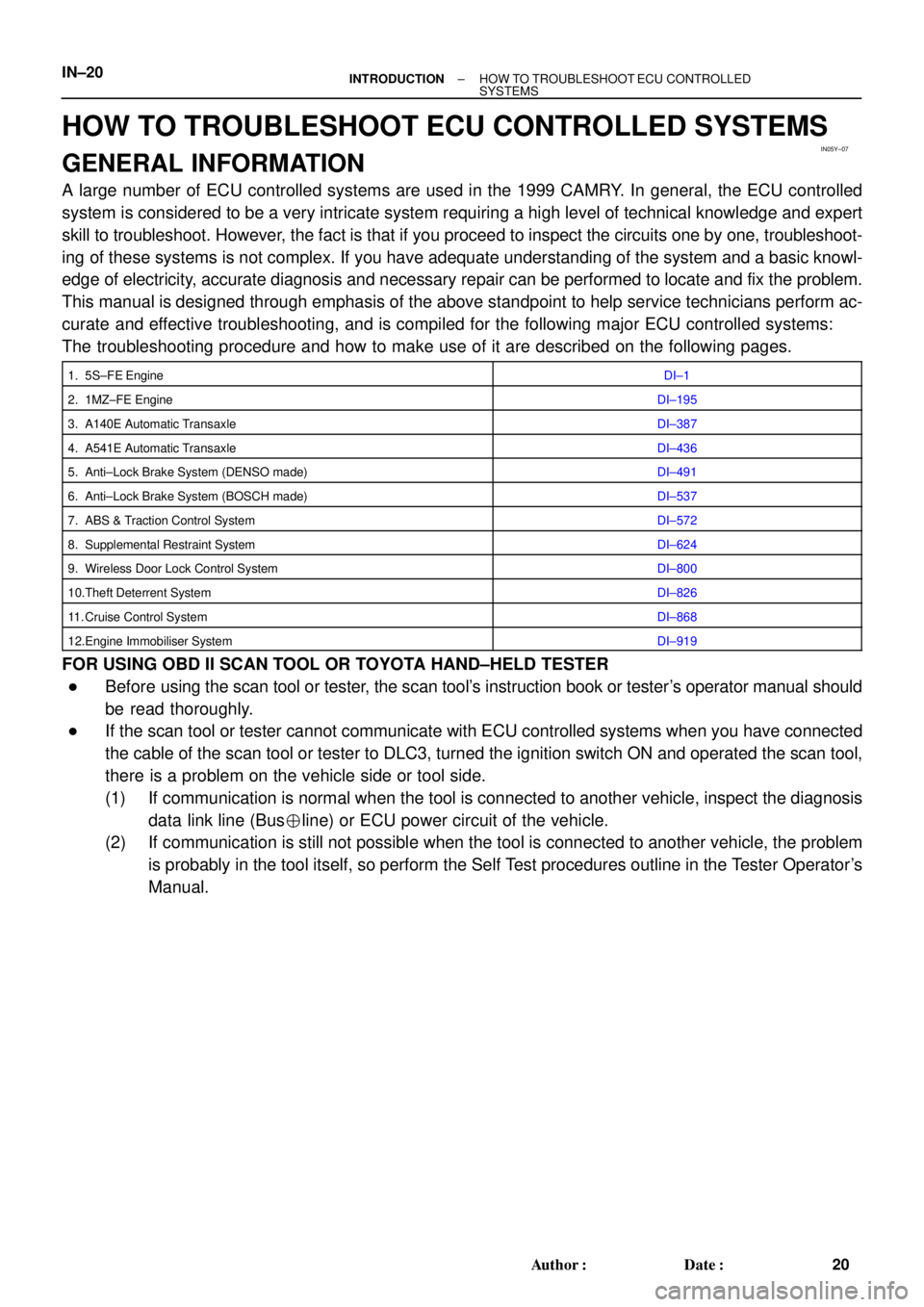
A large number of ECU controlled systems are used in the 1999 CAMRY. In general, the ECU controlled
system is considered to be a very intricate system requiring a high level of technical knowledge and expert
skill to troubleshoot. However, the fact is that if you proceed to inspect the circuits one by one, troubleshoot-
ing of these systems is not complex. If you have adequate understanding of the system and a basic knowl-
edge of electricity, accurate diagnosis and necessary repair can be performed to locate and fix the problem.
This manual is designed through emphasis of the above standpoint to help service technicians perform ac-
curate and effective troubleshooting, and is compiled for the following major ECU controlled systems:
The troubleshooting procedure and how to make use of it are described on the following pages.
1. 5S±FE EngineDI±1
2. 1MZ±FE EngineDI±195
3. A140E Automatic TransaxleDI±387
4. A541E Automatic TransaxleDI±436
5. Anti±Lock Brake System (DENSO made)DI±491
6. Anti±Lock Brake System (BOSCH made)DI±537
7. ABS & Traction Control SystemDI±572
8. Supplemental Restraint SystemDI±624
9. Wireless Door Lock Control SystemDI±800
10.Theft Deterrent SystemDI±826
11. Cruise Control SystemDI±868
12.Engine Immobiliser SystemDI±919
FOR USING OBD II SCAN TOOL OR TOYOTA HAND±HELD TESTER
�Before using the scan tool or tester, the scan tool's instruction book or tester's operator manual should
be read thoroughly.
�If the scan tool or tester cannot communicate with ECU controlled systems when you have connected
the cable of the scan tool or tester to DLC3, turned the ignition switch ON and operated the scan tool,
there is a problem on the vehicle side or tool side.
(1) If communication is normal when the tool is connected to another vehicle, inspect the diagnosis
data link line (Bus�line) or ECU power circuit of the vehicle.
(2) If communication is still not possible when the tool is connected to another vehicle, the problem
is probably in the tool itself, so perform the Self Test procedures outline in the Tester Operator's
Manual.
Page 2864 of 4592

IN05Y±10
IN±18± INTRODUCTIONHOW TO TROUBLESHOOT ECU CONTROLLED
SYSTEMS
18 Author�: Date�:
HOW TO TROUBLESHOOT ECU CONTROLLED SYSTEMS
GENERAL INFORMATION
A large number of ECU controlled systems are used in the 1999 CAMRY CNG. In general, the ECU con-
trolled system is considered to be a very intricate system requiring a high level of technical knowledge and
expert skill to troubleshoot. However, the fact is that if you proceed to inspect the circuits one by one, trouble-
shooting of these systems is not complex. If you have adequate understanding of the system and a basic
knowledge of electricity, accurate diagnosis and necessary repair can be performed to locate and fix the
problem. This manual is designed through emphasis of the above standpoint to help service technicians
perform accurate and effective troubleshooting, and is compiled for the following major ECU controlled sys-
tems:
The troubleshooting procedure and how to make use of it are described on the following pages.
1. EngineDI±1
2. Automatic TransaxleDI±131
3. Anti±Lock Brake SystemDI±175
4. Supplemental Restraint SystemDI±221
5. Cruise Control SystemDI±317
FOR USING OBD II SCAN TOOL OR HAND±HELD TESTER
�Before using the scan tool or tester, the scan tool's instruction book or tester's operator manual should
be read thoroughly.
�If the scan tool or tester cannot communicate with ECU controlled systems when you have connected
the cable of the scan tool or tester to DLC3, turned the ignition switch ON and operated the scan tool,
there is a problem on the vehicle side or tool side.
(1) If communication is normal when the tool is connected to another vehicle, inspect the diagnosis
data link line (Bus�line) or ECU power circuit of the vehicle.
(2) If communication is still not possible when the tool is connected to another vehicle, the problem
is probably in the tool itself, so perform the Self Test procedures outline in the Tester Operator's
Manual.
Page 4004 of 4592

M.I.L. ªONº 1MZ±FE ENGINE MISFIRE DTC P0300 ± P0306 ± EG008-04April 28, 2004
Page 3 of 3
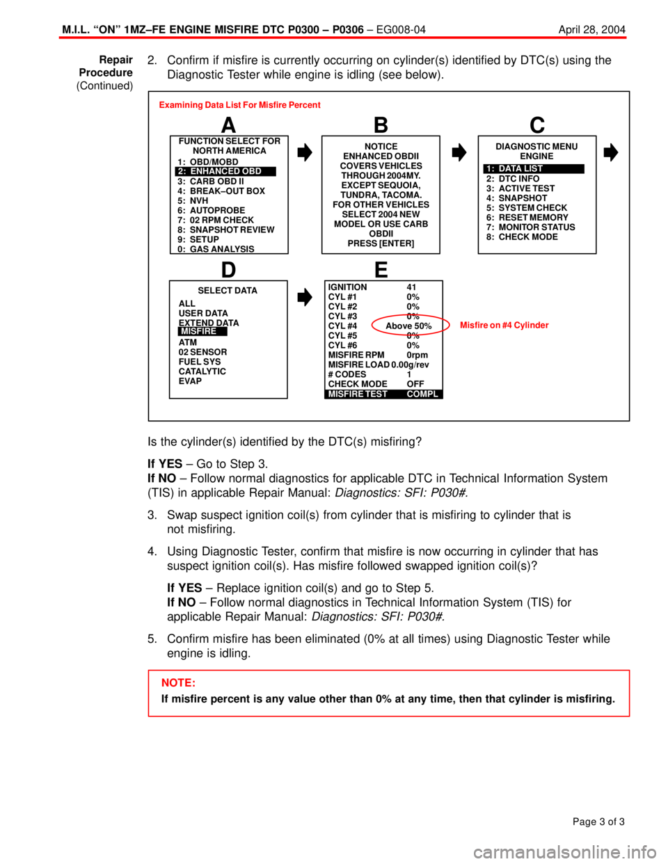
2. Confirm if misfire is currently occurring on cylinder(s) identified by DTC(s) using the
Diagnostic Tester while engine is idling (see below).
FUNCTION SELECT FOR
NORTH AMERICA
B A
DIAGNOSTIC MENU
ENGINE
C
ALL
USER DATA
EXTEND DATA
AT M
02 SENSOR
FUEL SYS
CATALYTIC
EVAP
E
SELECT DATA
D
MISFIRE
1: OBD/MOBD
3: CARB OBD II
4: BREAK±OUT BOX
5: NVH
6: AUTOPROBE
7: 02 RPM CHECK
8: SNAPSHOT REVIEW
9: SETUP
0: GAS ANALYSIS2: ENHANCED OBD
2: DTC INFO
3: ACTIVE TEST
4: SNAPSHOT
5: SYSTEM CHECK
6: RESET MEMORY
7: MONITOR STATUS
8: CHECK MODE1: DATA LIST Examining Data List For Misfire Percent
NOTICE
ENHANCED OBDII
COVERS VEHICLES
THROUGH 2004MY.
EXCEPT SEQUOIA,
TUNDRA, TACOMA.
FOR OTHER VEHICLES
SELECT 2004 NEW
MODEL OR USE CARB
OBDII
PRESS [ENTER]
IGNITION 41
CYL #1 0%
CYL #2 0%
CYL #3 0%
CYL #4 Above 50%
CYL #5 0%
CYL #6 0%
MISFIRE RPM 0rpm
MISFIRE LOAD 0.00g/rev
# CODES 1
CHECK MODE OFF
MISFIRE TEST COMPL
Misfire on #4 Cylinder
Is the cylinder(s) identified by the DTC(s) misfiring?
If YES ± Go to Step 3.
If NO ± Follow normal diagnostics for applicable DTC in Technical Information System
(TIS) in applicable Repair Manual:
Diagnostics: SFI: P030#.
3. Swap suspect ignition coil(s) from cylinder that is misfiring to cylinder that is
not misfiring.
4. Using Diagnostic Tester, confirm that misfire is now occurring in cylinder that has
suspect ignition coil(s). Has misfire followed swapped ignition coil(s)?
If YES ± Replace ignition coil(s) and go to Step 5.
If NO ± Follow normal diagnostics in Technical Information System (TIS) for
applicable Repair Manual:
Diagnostics: SFI: P030#.
5. Confirm misfire has been eliminated (0% at all times) using Diagnostic Tester while
engine is idling.
NOTE:
If misfire percent is any value other than 0% at any time, then that cylinder is misfiring. Repair
Procedure
(Continued)