Page 2978 of 4592
Z00292
SST
Z00293
SST
Z19038
FIPGF
± MANUAL TRANSAXLE (E153)DIFFERENTIAL CASE
MX±45
1846 Author�: Date�:
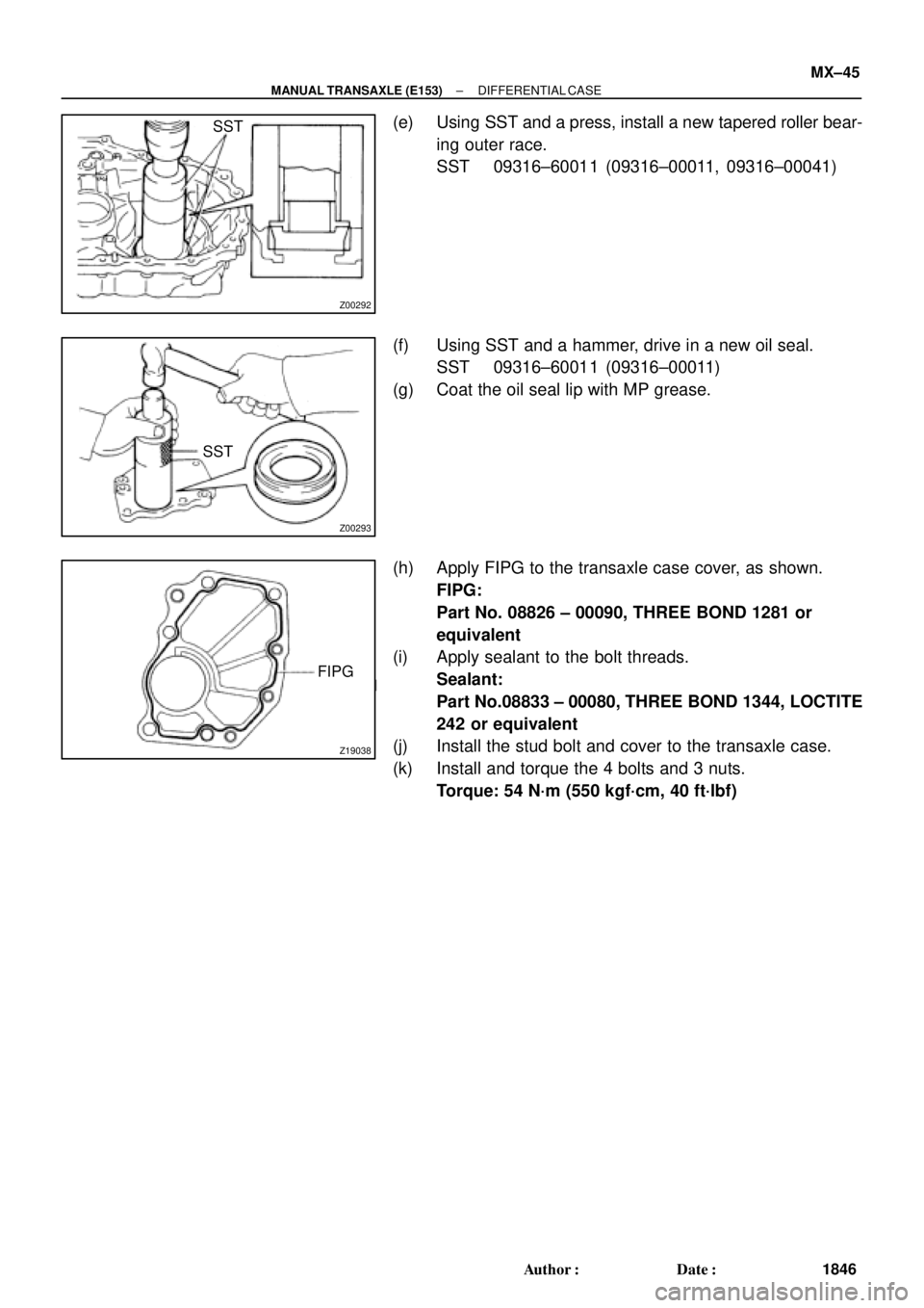
(e) Using SST and a press, install a new tapered roller bear-
ing outer race.
SST 09316±60011 (09316±00011, 09316±00041)
(f) Using SST and a hammer, drive in a new oil seal.
SST 09316±60011 (09316±00011)
(g) Coat the oil seal lip with MP grease.
(h) Apply FIPG to the transaxle case cover, as shown.
FIPG:
Part No. 08826 ± 00090, THREE BOND 1281 or
equivalent
(i) Apply sealant to the bolt threads.
Sealant:
Part No.08833 ± 00080, THREE BOND 1344, LOCTITE
242 or equivalent
(j) Install the stud bolt and cover to the transaxle case.
(k) Install and torque the 4 bolts and 3 nuts.
Torque: 54 N´m (550 kgf´cm, 40 ft´lbf)
Page 2979 of 4592
DIFFERENTIAL CASE
1847 Author�: Date�:
REASSEMBLY
1. ASSEMBLE DIFFERENTIAL CASE
HINT:
Coat all of the sliding and rotating surfac")
MX05J±01
Z00295
Z00296
Z00297
Z00298
MX±46
± MANUAL TRANSAXLE (E153)DIFFERENTIAL CASE
1847 Author�: Date�:
REASSEMBLY
1. ASSEMBLE DIFFERENTIAL CASE
HINT:
Coat all of the sliding and rotating surfaces with gear oil before
reassembly.
(a) Install the thrust washer to the side gear.
(b) Install the 4 pinions and thrust washers to the spider.
(c) Install the side gear and spider with the 4 pinions to the
differential left case.
(d) Using a dial indicator, measure the backlash of the pinion
gear while holding the differential left case.
Standard backlash:
0.05 ± 0.20 mm (0.0020 ± 0.0079 in.)
HINT:
Push the pinion gear and spider with the 4 pinions to the differ-
ential left case.
(e) Install the side gear and spider with the 4 pinions to the
right side of the differential case. Check the side gear
backlash.
(f) Refer to the table below, and select the thrust washer
which will ensure that the backlash is within the specifica-
tion. Try to select a washer of the same size.
Thickness mm (in.)Thickness mm (in.)
0.80 (0.0315)1.20 (0.0472)
0.90 (0.0354)1.30 (0.0512)
1.00 (0.0394)1.40 (0.0551)
1.10 (0.0433)±
(g) Install the vehicle speed sensor drive gear.
Page 2980 of 4592
DIFFERENTIAL CASE
MX±47
1848 Author�: Date�:
(h) Align the matchmarks on the differential cases.
(i) Using a plastic")
Z00299
Matchmarks
Z00303
Driven Gear
Side
Q06410
SST
SST
± MANUAL TRANSAXLE (E153)DIFFERENTIAL CASE
MX±47
1848 Author�: Date�:
(h) Align the matchmarks on the differential cases.
(i) Using a plastic hammer, carefully tap the differential case
to install it.
(j) Using a torx wrench (T50), install and torque the 16 torx
screws.
Torque: 63 N´m (640 kgf´cm, 46 ft´lbf)
2. INSTALL RING GEAR
(a) Clean the contact surface of the differential case and the
threads of the ring gear and differential case.
(b) Heat the ring gear in boiling water.
(c) Carefully remove the ring gear from the water.
(d) After the moisture on the ring gear has completely evapo-
rated, quickly install the ring gear to the differential case.
HINT:
Align the matchmarks on the differential left case.
(e) Temporarily install the 16 bolts.
NOTICE:
The ring gear set bolts should not be tightened until the
ring gear has cooled sufficiently.
(f) After the ring gear has cooled sufficiently, torque the ring
gear set bolts.
Torque: 124 N´m (1,260 kgf´cm, 91 ft´lbf)
3. INSTALL TAPERED ROLLER BEARING
Using SST and a press, install new left and right bearings onto
the differential case.
SST 09316±20011, 09316±60011 (09316±00011)
HINT:
Press the bearing on the ring side first.
4. ADJUST OUTPUT SHAFT ASSEMBLY PRELOAD
(See pages MX±22)
5. INSTALL DIFFERENTIAL CASE ASSEMBLY TO
TRANSAXLE CASE
6. INSTALL OUTPUT SHAFT ASSEMBLY
Lift up the differential case and install the output shaft assem-
bly.
7. INSTALL TRANSMISSION CASE
(a) Install the transmission case.
HINT:
If necessary, tap on the case with a plastic hammer.
(b) Install and torque the 17 bolts.
Torque: 29 N´m (300 kgf´cm 22 ft´lbf)
Page 2981 of 4592
DIFFERENTIAL CASE
1849 Author�: Date�:
8. INSTALL OUTPUT SHAFT REAR TAPERED ROLLER
BEARING OUTER RACE
Using a plastic hammer, drive in the outer race.
9.")
Q00036
Z00309
MX±48
± MANUAL TRANSAXLE (E153)DIFFERENTIAL CASE
1849 Author�: Date�:
8. INSTALL OUTPUT SHAFT REAR TAPERED ROLLER
BEARING OUTER RACE
Using a plastic hammer, drive in the outer race.
9. INSTALL SHIM (See pages MX±22)
HINT:
Install the previously selected shim.
10. INSTALL REAR BEARING RETAINER
Using a torx wrench (T45), install and torque the 7 torx screws.
Torque: 42 N´m (430 kgf´cm, 31 ft´lbf)
11. ADJUST DIFFERENTIAL CASE SIDE BEARING PRE-
LOAD
(a) Install a new lock nut to the output shaft.
(b) Turn the output shaft right and left 2 or 3 times to allow the
bearings to settle.
(c) Using a torque wrench, measure the preload.
Preload (at starting):
New bearing (Output shaft preload plus)
0.2 ± 0.3 N´m (1.8 ± 3.5 kgf´cm, 1.6 ± 3.0 in.´lbf)
Reused bearing (Output shaft preload plus)
0.1 ± 0.2 N´m (1.1 ± 2.2 kgf´cm, 1.0 ± 1.9 in.´lbf)
If the preload is not within the specification, select an appropri-
ate adjusting shim.
HINT:
The total preload will change by about 0.1 ± 0.2 N´m (1 ± 2
kgf´cm, 0.9 ± 1.7 in.´lbf) with each 0.05 mm change in adjusting
shim thickness.
MarkThickness mm (in.)MarkThickness mm (in.)
02.00 (0.0787)92.45 (0.0965)
12.05 (0.0807)A2.50 (0.0984)
22.10 (0.0827)B2.55 (0.1004)
32.15 (0.0846)C2.60 (0.1024)
42.20 (0.0866)D2.65 (0.1043)
52.25 (0.0886)E2.70 (0.1063)
62.30 (0.0906)F2.75 (0.1083)
72.35 (0.0925)G2.80 (0.1102)
82.40 (0.0945)H2.85 (0.1122)
12. REMOVE REAR BEARING RETAINER
Using a torx wrench (T45), remove the 7 torx screws and rear
bearing retainer.
13. REMOVE SHIM
14. REMOVE TRANSMISSION CASE
(a) Remove the 17 bolts.
(b) Using a plastic hammer, tap the transmission case.
15. REMOVE OUTPUT SHAFT ASSEMBLY
16. REMOVE DIFFERENTIAL CASE ASSEMBLY
Page 2991 of 4592

MX04F±02
Z19123
Transmission Case Cover5th Driven GearRear Bearing Retainer
No.3 Shift Fork N0.3 Hub Sleeve No.3 Clutch Hub Assembly Needle Roller BearingRelease ForkTransmission
CaseDifferential Side
Bearing Retainer
Transmission
Case Protector Straight Screw Plug
Shift and Select Lever
Assembly
Selecting Bellcrank Back±UP
Light SwitchLock Ball
Assembly Release Bearing
Retainer
Vehicle
Speed Sensor
Release
BearingReverse
Restrict Pin�
O±Ring �Shim
x 6 Slotted
Spring Pin
Gasket
Clutch Release Fork
Support
x 17
Snap RingLock Nut Filler Plug
Lock Boltx 5
Spacer
5th Gear
x 8 Boot
�
Gasket �
Gasket �Drain Plug
Snap Ring�
�
�
� �Non±reusable part
Precoated part: Specified torque
N´m (kgf´cm, ft´lbf)
5.4 (55, 48 in.´lbf)
13 (130, 9)
123 (1,250, 90)�
37 (375, 27)29 (300, 22)�
44 (450, 33)
18 (185, 13)
18 (185, 13)
42 (430, 31)
29 (300, 22)
29 (300, 22)
49 (500, 36)
39 (400, 29)
18 (185, 13)
29 (300, 22)
7.4 (75, 65 in.´lbf)
37 (380, 27)
± MANUAL TRANSAXLE (S51)MANUAL TRANSAXLE ASSEMBLY
MX±9
1859 Author�: Date�:
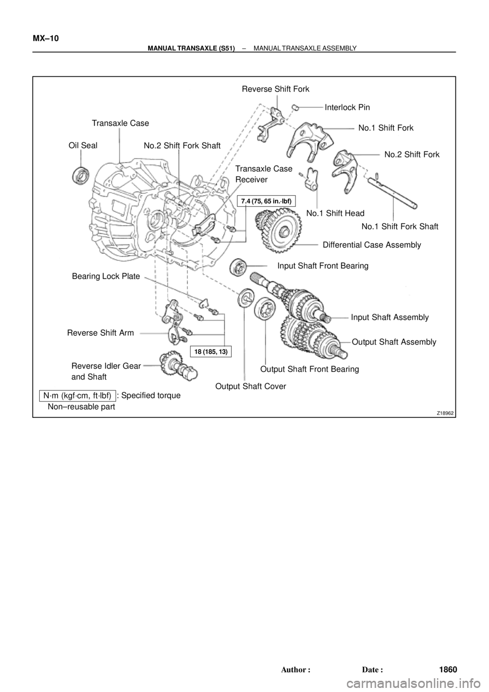
MANUAL TRANSAXLE ASSEMBLY
COMPONENTS
Page 2992 of 4592
Z18962�Non±reusable part: Specified torque
N´m (kgf´cm, ft´lbf)Transaxle Case
No.2 Shift Fork ShaftReverse Shift Fork
Interlock Pin
No.1 Shift Fork
No.1 Shift Fork Shaft No.1 Shift Head
Differential Case Assembly
Input Shaft Front Bearing
Input Shaft Assembly
Output Shaft CoverOutput Shaft Front Bearing Reverse Idler Gear
and Shaft Reverse Shift ArmBearing Lock PlateTransaxle Case
Receiver Oil Seal
No.2 Shift Fork
Output Shaft Assembly �
�
�
7.4 (75, 65 in.´lbf)
18 (185, 13)
MX±10
± MANUAL TRANSAXLE (S51)MANUAL TRANSAXLE ASSEMBLY
1860 Author�: Date�:
Page 2996 of 4592
MANUAL TRANSAXLE ASSEMBLY
1864 Author�: Date�:
HINT:
At the time of installation, please refer to the following item.")
Q02682
SST
Q05785
x 5
Q05826
x 17
x 6
Q09474FIPG MX±14
± MANUAL TRANSAXLE (S51)MANUAL TRANSAXLE ASSEMBLY
1864 Author�: Date�:
HINT:
At the time of installation, please refer to the following item.
Using SST and a press, install the No.3 clutch hub assembly.
SST 09612±22011
(c) Remove the 5th gear.
15. REMOVE NEEDLE ROLLER BEARING
16. REMOVE REAR BEARING RETAINER
Remove the 5 bolts and retainer.
Sealant:
Part No.08833 ± 00070, THREE BOND 1324 or equiva-
lent
Torque: 42 N´m (430 kgf´cm, 31 ft´lbf)
17. REMOVE BEARING SNAP RING
Using a snap ring expander, remove the 2 snap rings.
HINT:
If it is difficult to remove and install the snap rings, pull up the
shafts.
18. REMOVE REVERSE IDLER GEAR SHAFT LOCK BOLT
AND GASKET
Torque: 29 N´m (300 kgf´cm, 22 ft´lbf)
19. REMOVE DIFFERENTIAL SIDE BEARING RETAINER
AND SHIM
Remove the 6 bolts, retainer and shim.
Sealant:
Part No.08833 ± 00080, THREE BOND 1344, LOCTITE
242 or equivalent
Torque: 18 N´m (185 kgf´cm, 13 ft´lbf)
20. REMOVE TRANSMISSION CASE
(a) Remove the 17 bolts.
Torque: 29 N´m (300 kgf´cm, 22 ft´lbf)
(b) Using a plastic hammer, tap the transmission case and re-
move it.
FIPG:
Part No. 08833 ± 00090, THREE BOND 1281 or equiva-
lent
Page 2997 of 4592
MANUAL TRANSAXLE ASSEMBLY
MX±15
1865 Author�: Date�:
21. REMOVE REVERSE IDLER GEAR AND SHAFT
(a) Pull out the shaft.
(b) Remove the idler gear and thrust washer")
Q05827
Q03065
± MANUAL TRANSAXLE (S51)MANUAL TRANSAXLE ASSEMBLY
MX±15
1865 Author�: Date�:
21. REMOVE REVERSE IDLER GEAR AND SHAFT
(a) Pull out the shaft.
(b) Remove the idler gear and thrust washer.
22. REMOVE REVERSE SHIFT ARM
(a) Shift the fork shaft into reverse.
(b) Remove the 2 bolts and pull off the reverse shift arm.
Torque: 18 N´m (185 kgf´cm, 13 ft´lbf)
23. REMOVE NO.1 SHIFT FORK SHAFT, NO.1 SHIFT
HEAD, NO.1 AND NO.2 SHIFT FORKS, REVERSE
SHIFT FORK WITH INTERLOCK PIN, INPUT AND OUT-
PUT SHAFTS ASSEMBLY
24. REMOVE DIFFERENTIAL CASE ASSEMBLY
25. REMOVE MAGNET FROM TRANSAXLE CASE
26. REMOVE NO.2 SHIFT FORK SHAFT
(a) Using a hexagon wrench, remove the straight screw plug.
Sealant:
Part No.08833 ± 00080, THREE BOND 1344, LOCTITE
242 or equivalent
Torque: 13 N´m (130 kgf´cm, 9 ft´lbf)
(b) Using a pin punch and hammer, drive out the slotted
spring pin.
(c) Pull out the shaft.
27. SEPARATE NO.1 SHIFT FORK SHAFT, NO.1 SHIFT
HEAD, NO.1, NO.2 SHIFT FORKS AND REVERSE
SHIFT FORK
(a) Mount the shift forks to the vise.
(b) Using a pin punch and hammer, drive out the slotted
spring pin from the No.1 fork shaft.
(c) Using a pin punch and hammer, drive out the slotted
spring pin from the No.1 fork shaft, as shown.
(d) Separate the No.1 shift fork shaft, No.1 shift head, No.1
and No.2 shift forks and reverse shift fork.