Page 2811 of 4592
IN0CP±03
N20619
Front
JACK POSITION
Front..................... Front crossmember
Rear..................... Rear axle beam
CAUTION :
PANTOGRAPH JACK POSITION
SUPPORT POSITION
Safety stand and swing arm type lift ...........................................When jacking±up the rear and front, make
sure the car is not carrying any extra weight.
IN±8
± INTRODUCTIONREPAIR INSTRUCTIONS
8 Author�: Date�:
VEHICLE LIFT AND SUPPORT LOCATIONS
Page 2839 of 4592

IN04Q±03
IN±36
± INTRODUCTIONTERMS
36 Author�: Date�:
TERMS
ABBREVIATIONS USED IN THIS MANUAL
AbbreviationsMeaning
ABSAnti±Lock Brake System
ACAlternating Current
ACCAccessory
ACISAcoustic Control Induction System
ACSDAutomatic Cold Start Device
A.D.D.Automatic Disconnecting Differential
A/FAir±Fuel Ratio
AHCActive Height Control Suspension
ALRAutomatic Locking Retractor
ALTAlternator
AMPAmplifier
ANTAntenna
APPROX.Approximately
A/TAutomatic Transmission (Transaxle)
AT FAutomatic Transmission Fluid
AUTOAutomatic
AUXAuxiliary
AV GAverage
AV SAdaptive Variable Suspension
BACSBoost Altitude Compensation System
BATBattery
BDCBottom Dead Center
B/LBi±Level
B/SBore±Stroke Ratio
BTDCBefore Top Dead Center
BVSVBimetallic Vacuum Switching Valve
Calif.California
CBCircuit Breaker
CCoCatalytic Converter For Oxidation
CDCompact Disc
CFCornering Force
CGCenter Of Gravity
CHChannel
COMB.Combination
CPECoupe
CPSCombustion Pressure Sensor
CPUCentral Processing Unit
CRSChild Restraint System
CTRCenter
C/VCheck Valve
CVControl Valve
CWCurb Weight
Page 2854 of 4592
IN0CP±05
N20619
Front
JACK POSITION
Front..................... Front crossmember
Rear..................... Rear axle beam
CAUTION :
PANTOGRAPH JACK POSITION
SUPPORT POSITION
Safety stand and swing arm type lift ...........................................When jacking±up the rear and front, make
sure the car is not carrying any extra weight.
IN±8
± INTRODUCTIONREPAIR INSTRUCTIONS
VEHICLE LIFT AND SUPPORT LOCATIONS
Page 2880 of 4592

IN04Q±03
IN±34
± INTRODUCTIONTERMS
34 Author�: Date�:
TERMS
ABBREVIATIONS USED IN THIS MANUAL
AbbreviationsMeaning
ABSAnti±Lock Brake System
ACAlternating Current
ACCAccessory
ACISAcoustic Control Induction System
ACSDAutomatic Cold Start Device
A.D.D.Automatic Disconnecting Differential
A/FAir±Fuel Ratio
AHCActive Height Control Suspension
ALRAutomatic Locking Retractor
ALTAlternator
AMPAmplifier
ANTAntenna
APPROX.Approximately
A/TAutomatic Transmission (Transaxle)
AT FAutomatic Transmission Fluid
AUTOAutomatic
AUXAuxiliary
AV GAverage
AV SAdaptive Variable Suspension
BACSBoost Altitude Compensation System
BATBattery
BDCBottom Dead Center
B/LBi±Level
B/SBore±Stroke Ratio
BTDCBefore Top Dead Center
BVSVBimetallic Vacuum Switching Valve
Calif.California
CBCircuit Breaker
CCoCatalytic Converter For Oxidation
CDCompact Disc
CFCornering Force
CGCenter Of Gravity
CHChannel
COMB.Combination
CPECoupe
CPSCombustion Pressure Sensor
CPUCentral Processing Unit
CRSChild Restraint System
CTRCenter
C/VCheck Valve
CVControl Valve
CWCurb Weight
Page 2897 of 4592

LU03M±03
S01170
S01483
S01484
LU±10
± LUBRICATION (5S±FE)OIL PUMP
1656 Author�: Date�:
INSPECTION
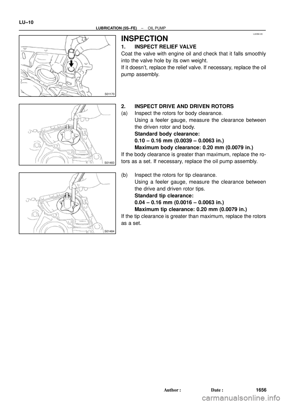
1. INSPECT RELIEF VALVE
Coat the valve with engine oil and check that it falls smoothly
into the valve hole by its own weight.
If it doesn't, replace the relief valve. If necessary, replace the oil
pump assembly.
2. INSPECT DRIVE AND DRIVEN ROTORS
(a) Inspect the rotors for body clearance.
Using a feeler gauge, measure the clearance between
the driven rotor and body.
Standard body clearance:
0.10 ± 0.16 mm (0.0039 ± 0.0063 in.)
Maximum body clearance: 0.20 mm (0.0079 in.)
If the body clearance is greater than maximum, replace the ro-
tors as a set. If necessary, replace the oil pump assembly.
(b) Inspect the rotors for tip clearance.
Using a feeler gauge, measure the clearance between
the drive and driven rotor tips.
Standard tip clearance:
0.04 ± 0.16 mm (0.0016 ± 0.0063 in.)
Maximum tip clearance: 0.20 mm (0.0079 in.)
If the tip clearance is greater than maximum, replace the rotors
as a set.
Page 2917 of 4592

LU02A±03
P12419
P12807
Mark
P12597
P12593
P12592
LU±12
± LUBRICATION (1MZ±FE)OIL PUMP
1676 Author�: Date�:
INSPECTION
1. INSPECT RELIEF VALVE
Coat the valve with engine oil and check that it falls smoothly
into the valve hole by its own weight.
If it does not, replace the relief valve. If necessary, replace the
oil pump assembly.
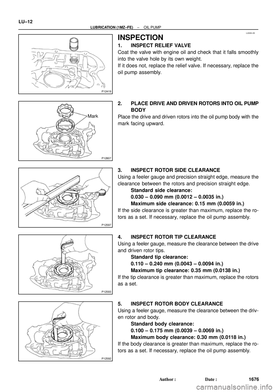
2. PLACE DRIVE AND DRIVEN ROTORS INTO OIL PUMP
BODY
Place the drive and driven rotors into the oil pump body with the
mark facing upward.
3. INSPECT ROTOR SIDE CLEARANCE
Using a feeler gauge and precision straight edge, measure the
clearance between the rotors and precision straight edge.
Standard side clearance:
0.030 ± 0.090 mm (0.0012 ± 0.0035 in.)
Maximum side clearance: 0.15 mm (0.0059 in.)
If the side clearance is greater than maximum, replace the ro-
tors as a set. If necessary, replace the oil pump assembly.
4. INSPECT ROTOR TIP CLEARANCE
Using a feeler gauge, measure the clearance between the drive
and driven rotor tips.
Standard tip clearance:
0.110 ± 0.240 mm (0.0043 ± 0.0094 in.)
Maximum tip clearance: 0.35 mm (0.0138 in.)
If the tip clearance is greater than maximum, replace the rotors
as a set.
5. INSPECT ROTOR BODY CLEARANCE
Using a feeler gauge, measure the clearance between the driv-
en rotor and body.
Standard body clearance:
0.100 ± 0.175 mm (0.0039 ± 0.0069 in.)
Maximum body clearance: 0.30 mm (0.0118 in.)
If the body clearance is greater than maximum, replace the ro-
tors as a set. If necessary, replace the oil pump assembly.
Page 3175 of 4592

H06696
SST
H00401Weight
x y
y
R04211
Inner Diam.
Tires
(3 or More)Width
± SUPPLEMENTAL RESTRAINT SYSTEMSTEERING WHEEL PAD AND SPIRAL CABLE
RS±23
2168 Author�: Date�:
(e) Install the SST.
CAUTION:
Place the disc wheel on the level ground.
(1) Connect the connector of SST to the steering wheel
pad connector.
SST 09082±00700
NOTICE:
To avoid damaging the SST connector and wire harness,
do not lock the secondary lock of the twin lock. Also, se-
cure some slack for the SST wire harness inside the disc
wheel.
(2) Move the SST to at least 10 m (33 ft) away from the
steering wheel pad tied down on the disc wheel.
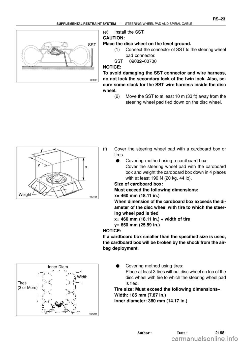
(f) Cover the steering wheel pad with a cardboard box or
tires.
�Covering method using a cardboard box:
Cover the steering wheel pad with the cardboard
box and weight the cardboard box down in 4 places
with at least 190 N (20 kg, 44 lb).
Size of cardboard box:
Must exceed the following dimensions:
x= 460 mm (18.11 in.)
When dimension of the cardboard box exceeds the di-
ameter of the disc wheel with tire to which the steer-
ing wheel pad is tied
x= 460 mm (18.11 in.) + width of tire
y= 650 mm (25.59 in.)
NOTICE:
If a cardboard box smaller than the specified size is used,
the cardboard box will be broken by the shock from the air-
bag deployment.
�Covering method using tires:
Place at least 3 tires without disc wheel on top of the
disc wheel with tire to which the steering wheel pad
is tied.
Tire size: Must exceed the following dimensions±
Width: 185 mm (7.87 in.)
Inner diameter: 360 mm (14.17 in.)
Page 3530 of 4592

R13897
Inscribed Mark
R11288
R07591
Compressed Air
R11563Inscribed Mark SR±24
± STEERINGPOWER STEERING VANE PUMP
2119 Author�: Date�:
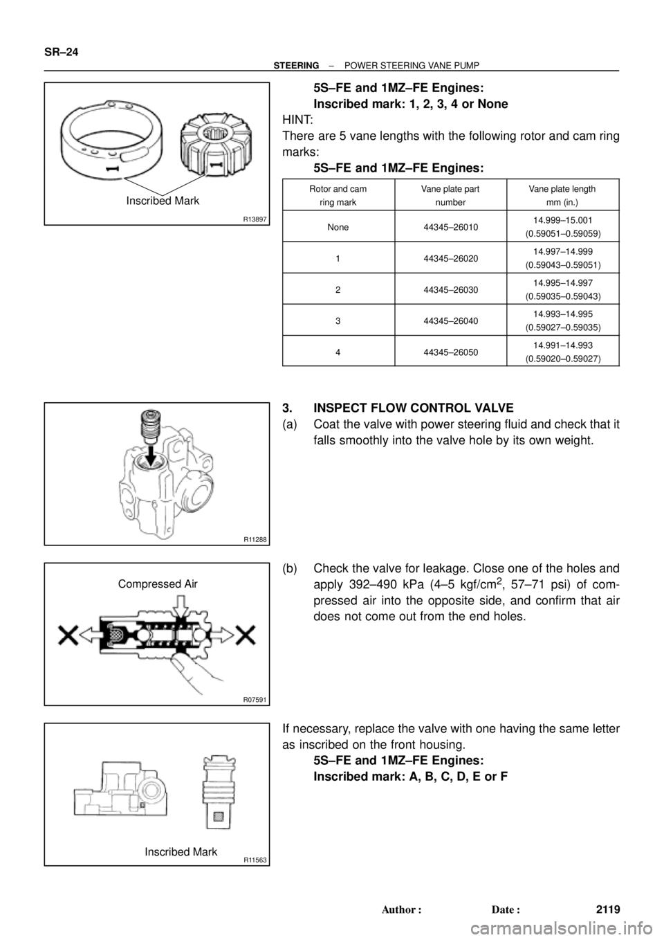
5S±FE and 1MZ±FE Engines:
Inscribed mark: 1, 2, 3, 4 or None
HINT:
There are 5 vane lengths with the following rotor and cam ring
marks:
5S±FE and 1MZ±FE Engines:
Rotor and cam
ring markVane plate part
numberVane plate length
mm (in.)
None44345±2601014.999±15.001
(0.59051±0.59059)
144345±2602014.997±14.999
(0.59043±0.59051)
244345±2603014.995±14.997
(0.59035±0.59043)
344345±2604014.993±14.995
(0.59027±0.59035)
444345±2605014.991±14.993
(0.59020±0.59027)
3. INSPECT FLOW CONTROL VALVE
(a) Coat the valve with power steering fluid and check that it
falls smoothly into the valve hole by its own weight.
(b) Check the valve for leakage. Close one of the holes and
apply 392±490 kPa (4±5 kgf/cm
2, 57±71 psi) of com-
pressed air into the opposite side, and confirm that air
does not come out from the end holes.
If necessary, replace the valve with one having the same letter
as inscribed on the front housing.
5S±FE and 1MZ±FE Engines:
Inscribed mark: A, B, C, D, E or F