Page 3573 of 4592

SA08Q±01
FA1535
SST
W03093
W03142
± SUSPENSION AND AXLEFRONT DRIVE SHAFT (5S±FE)
SA±17
1968 Author�: Date�:
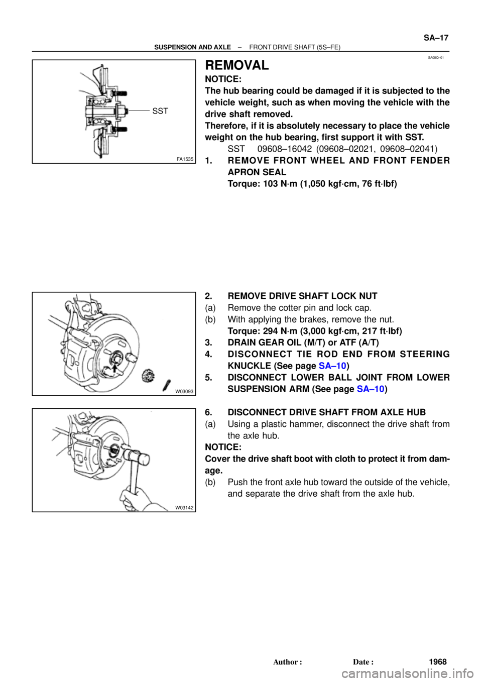
REMOVAL
NOTICE:
The hub bearing could be damaged if it is subjected to the
vehicle weight, such as when moving the vehicle with the
drive shaft removed.
Therefore, if it is absolutely necessary to place the vehicle
weight on the hub bearing, first support it with SST.
SST 09608±16042 (09608±02021, 09608±02041)
1. REMOVE FRONT WHEEL AND FRONT FENDER
APRON SEAL
Torque: 103 N´m (1,050 kgf´cm, 76 ft´lbf)
2. REMOVE DRIVE SHAFT LOCK NUT
(a) Remove the cotter pin and lock cap.
(b) With applying the brakes, remove the nut.
Torque: 294 N´m (3,000 kgf´cm, 217 ft´lbf)
3. DRAIN GEAR OIL (M/T) or ATF (A/T)
4. DISCONNECT TIE ROD END FROM STEERING
KNUCKLE (See page SA±10)
5. DISCONNECT LOWER BALL JOINT FROM LOWER
SUSPENSION ARM (See page SA±10)
6. DISCONNECT DRIVE SHAFT FROM AXLE HUB
(a) Using a plastic hammer, disconnect the drive shaft from
the axle hub.
NOTICE:
Cover the drive shaft boot with cloth to protect it from dam-
age.
(b) Push the front axle hub toward the outside of the vehicle,
and separate the drive shaft from the axle hub.
Page 3634 of 4592

SA1JR±01
FA1535
SST
W03093
W03094
SST
W03095
SA±6
± SUSPENSION AND AXLEFRONT DRIVE SHAFT
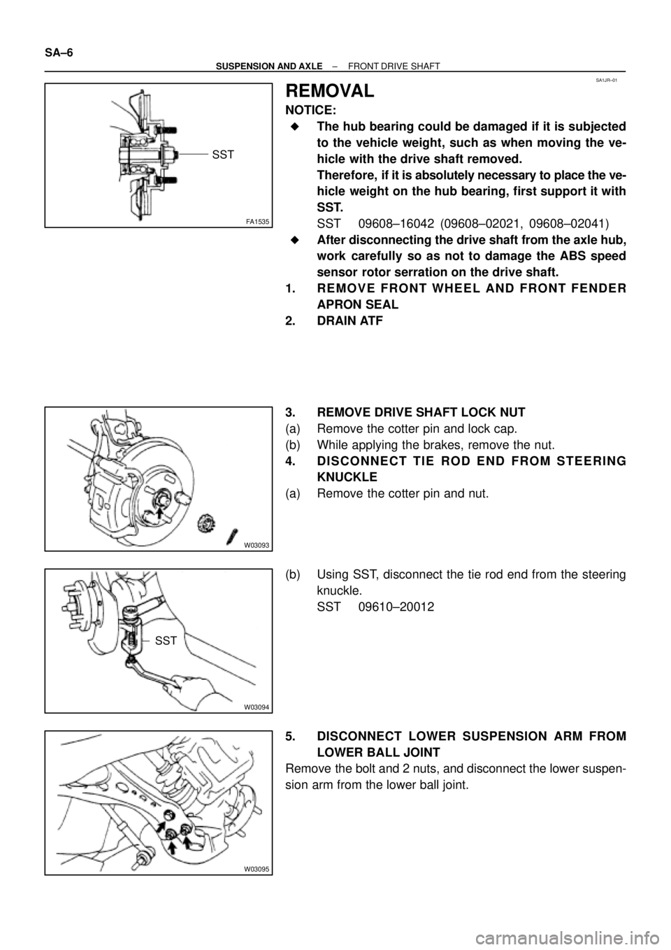
REMOVAL
NOTICE:
�The hub bearing could be damaged if it is subjected
to the vehicle weight, such as when moving the ve-
hicle with the drive shaft removed.
Therefore, if it is absolutely necessary to place the ve-
hicle weight on the hub bearing, first support it with
SST.
SST 09608±16042 (09608±02021, 09608±02041)
�After disconnecting the drive shaft from the axle hub,
work carefully so as not to damage the ABS speed
sensor rotor serration on the drive shaft.
1. REMOVE FRONT WHEEL AND FRONT FENDER
APRON SEAL
2. DRAIN ATF
3. REMOVE DRIVE SHAFT LOCK NUT
(a) Remove the cotter pin and lock cap.
(b) While applying the brakes, remove the nut.
4. DISCONNECT TIE ROD END FROM STEERING
KNUCKLE
(a) Remove the cotter pin and nut.
(b) Using SST, disconnect the tie rod end from the steering
knuckle.
SST 09610±20012
5. DISCONNECT LOWER SUSPENSION ARM FROM
LOWER BALL JOINT
Remove the bolt and 2 nuts, and disconnect the lower suspen-
sion arm from the lower ball joint.
Page 3813 of 4592

Toyota Supports ASE CertificationPage 1 of 1
EG007-02Title:
GENERAL MAINTENANCE TIP
Models:
All '93 ± '03 Models
Technical Service
BULLETIN
March 22, 2002
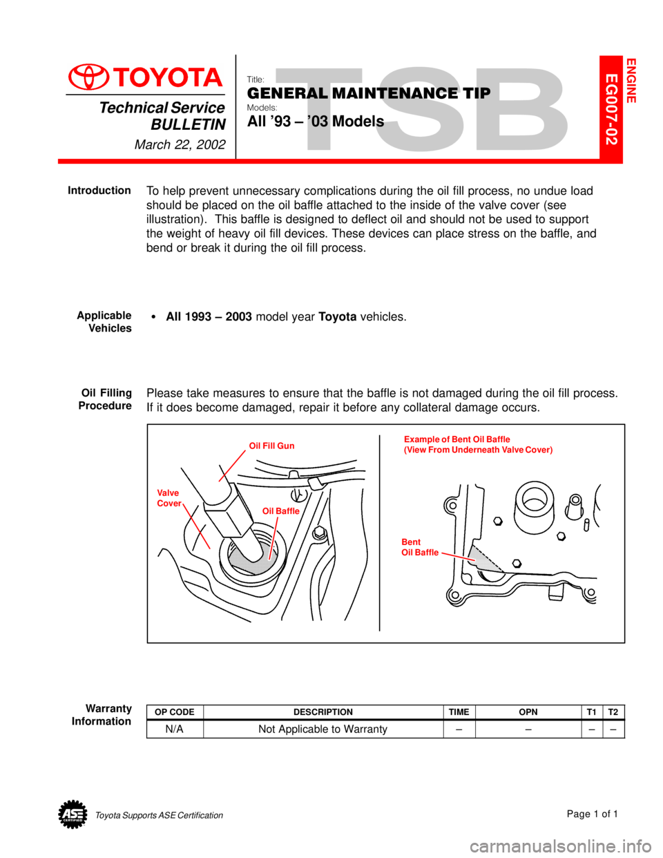
To help prevent unnecessary complications during the oil fill process, no undue load
should be placed on the oil baffle attached to the inside of the valve cover (see
illustration). This baffle is designed to deflect oil and should not be used to support
the weight of heavy oil fill devices. These devices can place stress on the baffle, and
bend or break it during the oil fill process.
�All 1993 ± 2003 model year Toyota vehicles.
Please take measures to ensure that the baffle is not damaged during the oil fill process.
If it does become damaged, repair it before any collateral damage occurs.
Oil Fill Gun
Oil BaffleExample of Bent Oil Baffle
(View From Underneath Valve Cover)
Bent
Oil Baffle
Valve
Cover
OP CODEDESCRIPTIONTIMEOPNT1T2
N/ANot Applicable to Warranty±±±±
ENGINE
Introduction
Applicable
Vehicles
Oil Filling
Procedure
Warranty
Information
Page 3944 of 4592

TSB
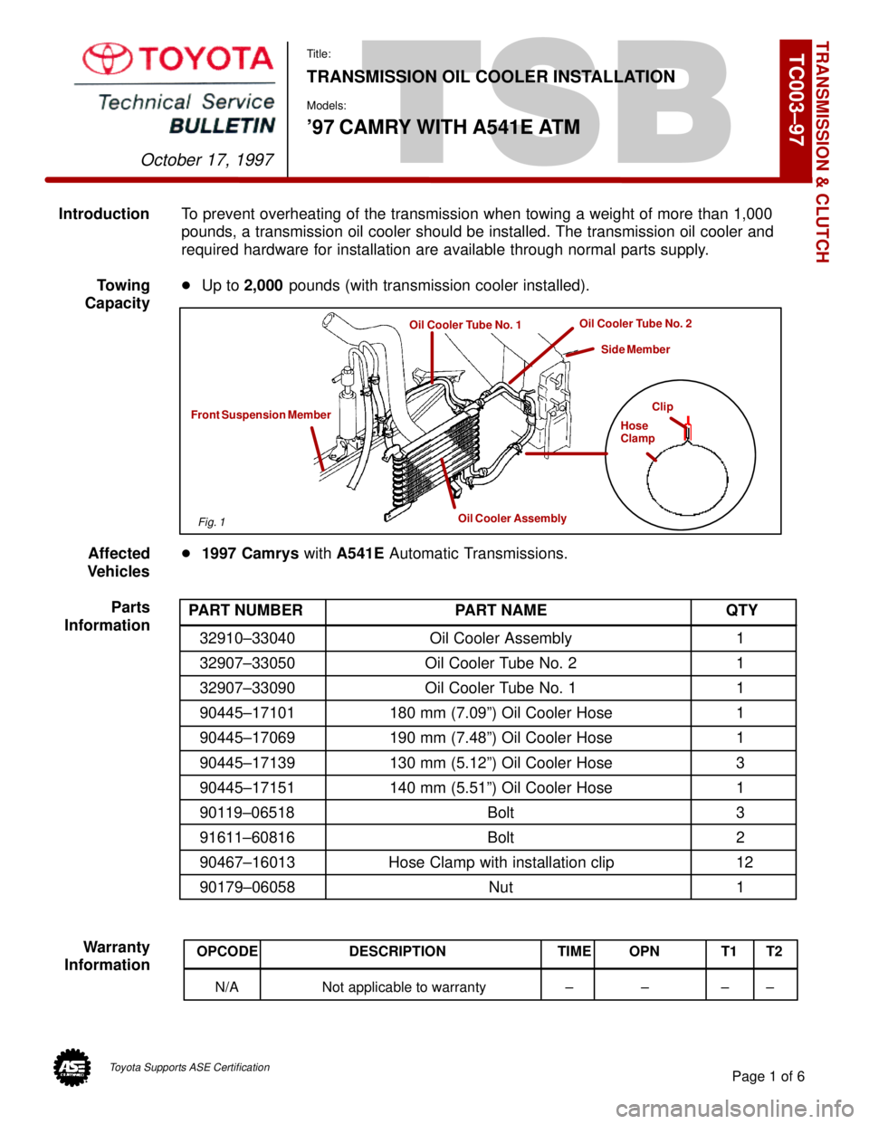
IntroductionTo prevent overheating of the transmission when towing a weight of more than 1,000
pounds, a transmission oil cooler should be installed. The transmission oil cooler and
required hardware for installation are available through normal parts supply.
Towing�Up to 2,000 pounds (with transmission cooler installed).
Capacity
Affected�1997 Camrys with A541E Automatic Transmissions.
Vehicles
Parts
Information
Warranty
Information
TRANSMISSION & CLUTCH
October 17, 1997
Title:
TRANSMISSION OIL COOLER INSTALLATION
Models:
'97 CAMRY WITH A541E ATM
Page 1 of 6
TC003±97
Clip
Hose
Clamp
Oil Cooler Assembly
Front Suspension Member
Oil Cooler Tube No. 1Oil Cooler Tube No. 2
Side Member
PART NUMBER PART NAME QTY
32910±33040 Oil Cooler Assembly 1
32907±33050 Oil Cooler Tube No. 2 1
32907±33090 Oil Cooler Tube No. 1 1
90445±17101 180 mm (7.09º) Oil Cooler Hose 1
90445±17069 190 mm (7.48º) Oil Cooler Hose 1
90445±17139 130 mm (5.12º) Oil Cooler Hose 3
90445±17151 140 mm (5.51º) Oil Cooler Hose 1
90119±06518 Bolt 3
91611±60816 Bolt 2
90467±16013 Hose Clamp with installation clip 12
90179±06058 Nut 1
OPCODE DESCRIPTION TIME OPN T1 T2
N/A Not applicable to warranty ± ± ± ±
Fig. 1
Toyota Supports ASE Certification