Page 2592 of 4592
EM089±03
P03265
SST
P03266
± ENGINE MECHANICAL (5S±FE)CYLINDER HEAD
EM±41
1213 Author�: Date�:
DISASSEMBLY
1. REMOVE CAMSHAFT POSITION SENSOR AS-
SEMBLY
Remove the bolt and sensor assembly.
2. REMOVE VALVE LIFTERS AND SHIMS
HINT:
Arrange the valve lifters and shims in the correct order.
3. REMOVE VALVES
(a) Using SST, compress the valve spring and remove the 2
keepers.
SST 09202±70020 (09202±00010)
(b) Remove the spring retainer, valve spring, valve and
spring seat.
HINT:
Arrange the valves, valve springs, spring seats and spring re-
tainers in the correct order.
(c) Using needle±nose pliers, remove the oil seal.
Page 2596 of 4592

EM2534
Overall Length
EM0255
P03272
45° Carbide
Cutter
Z00055
Width
± ENGINE MECHANICAL (5S±FE)CYLINDER HEAD
EM±45
1217 Author�: Date�:
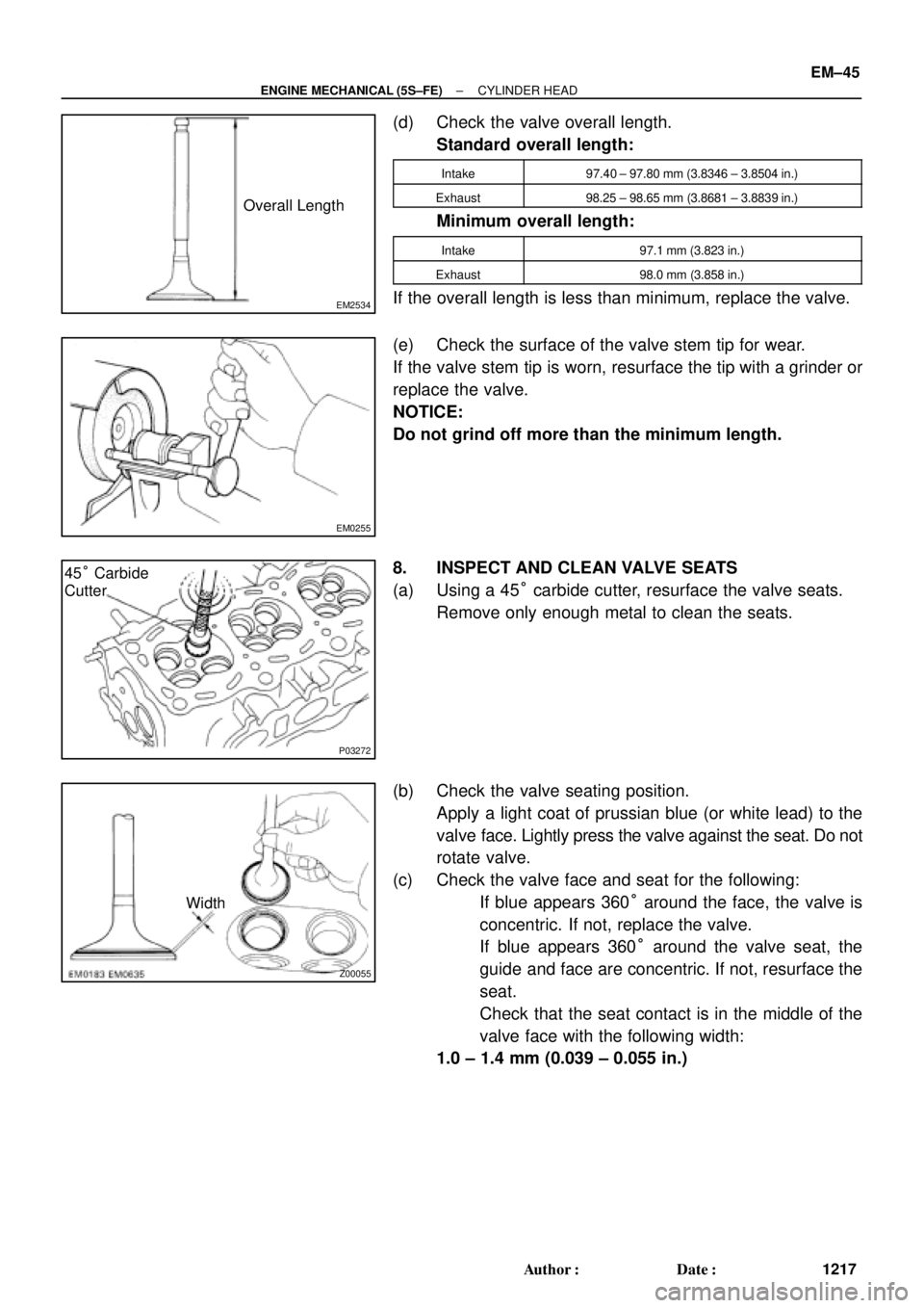
(d) Check the valve overall length.
Standard overall length:
Intake97.40 ± 97.80 mm (3.8346 ± 3.8504 in.)
Exhaust98.25 ± 98.65 mm (3.8681 ± 3.8839 in.)
Minimum overall length:
Intake97.1 mm (3.823 in.)
Exhaust98.0 mm (3.858 in.)
If the overall length is less than minimum, replace the valve.
(e) Check the surface of the valve stem tip for wear.
If the valve stem tip is worn, resurface the tip with a grinder or
replace the valve.
NOTICE:
Do not grind off more than the minimum length.
8. INSPECT AND CLEAN VALVE SEATS
(a) Using a 45° carbide cutter, resurface the valve seats.
Remove only enough metal to clean the seats.
(b) Check the valve seating position.
Apply a light coat of prussian blue (or white lead) to the
valve face. Lightly press the valve against the seat. Do not
rotate valve.
(c) Check the valve face and seat for the following:
�If blue appears 360° around the face, the valve is
concentric. If not, replace the valve.
�If blue appears 360° around the valve seat, the
guide and face are concentric. If not, resurface the
seat.
�Check that the seat contact is in the middle of the
valve face with the following width:
1.0 ± 1.4 mm (0.039 ± 0.055 in.)
Page 2597 of 4592
Z02852
45°
30°
1.0 ± 1.4 mm
Z02853
45° 75°
1.0 ± 1.4 mm
P03273
EM0988
Deviation
EM0801
EM±46
± ENGINE MECHANICAL (5S±FE)CYLINDER HEAD
1218 Author�: Date�:
If not, correct the valve seats as follows:
(1) If the seating is too high on the valve face, use 30°
and 45° cutters to correct the seat.
(2) If the seating is too low on the valve face, use 75°
and 45° cutters to correct the seat.
(d) Hand±lap the valve and valve seat with an abrasive com-
pound.
(e) After hand±lapping, clean the valve and valve seat.
9. INSPECT VALVE SPRINGS
(a) Using a steel square, measure the deviation of the valve
spring.
Maximum deviation: 2.0 mm (0.079 in.)
If the deviation is greater than maximum, replace the valve
spring.
(b) Using a vernier caliper, measure the free length of the
valve spring.
Free length: 40.95 ± 42.80 mm (1.6122 ± 1.6850 in.)
If the free length is not as specified, replace the valve spring.
Page 2707 of 4592
EM04T±03
P12683
P12476
SST
P12686
P12720
Magnetic Finger EM±42
± ENGINE MECHANICAL (1MZ±FE)CYLINDER HEAD
1328 Author�: Date�:
DISASSEMBLY
1. REMOVE VALVE LIFTERS AND SHIMS
HINT:
Arrange the valve lifters and shims in the correct order.
2. REMOVE VALVES
(a) Using SST, compress the valve spring and remove the 2
keepers.
SST 09202±70020 (09202±00010)
(b) Remove the spring retainer, valve spring and valve.
(c) Using needle±nose pliers, remove the oil seal.
(d) Using compressed air and a magnetic finger, remove the
spring seat by blowing air.
HINT:
Arrange the valves, valve springs, spring seats and spring re-
tainers in the correct order.
Page 2711 of 4592

EM2534
Overall Length
EM0255
P12704
P12729
Width
Z03988
45°
1.0 ± 1.4 mm30° EM±46
± ENGINE MECHANICAL (1MZ±FE)CYLINDER HEAD
1332 Author�: Date�:
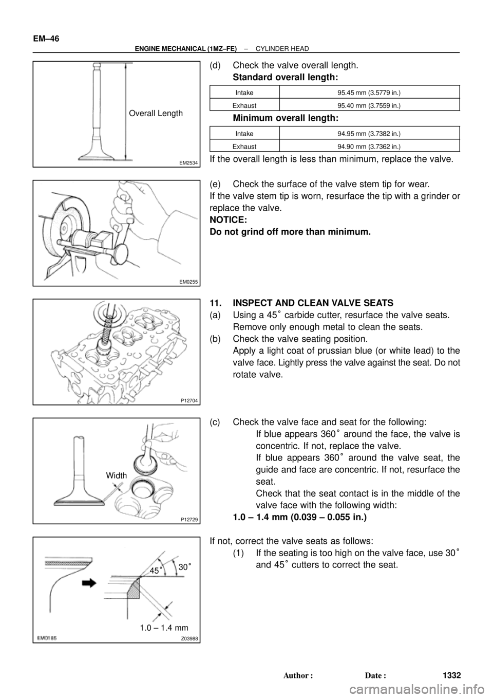
(d) Check the valve overall length.
Standard overall length:
Intake95.45 mm (3.5779 in.)
Exhaust95.40 mm (3.7559 in.)
Minimum overall length:
Intake94.95 mm (3.7382 in.)
Exhaust94.90 mm (3.7362 in.)
If the overall length is less than minimum, replace the valve.
(e) Check the surface of the valve stem tip for wear.
If the valve stem tip is worn, resurface the tip with a grinder or
replace the valve.
NOTICE:
Do not grind off more than minimum.
11. INSPECT AND CLEAN VALVE SEATS
(a) Using a 45° carbide cutter, resurface the valve seats.
Remove only enough metal to clean the seats.
(b) Check the valve seating position.
Apply a light coat of prussian blue (or white lead) to the
valve face. Lightly press the valve against the seat. Do not
rotate valve.
(c) Check the valve face and seat for the following:
�If blue appears 360° around the face, the valve is
concentric. If not, replace the valve.
�If blue appears 360° around the valve seat, the
guide and face are concentric. If not, resurface the
seat.
�Check that the seat contact is in the middle of the
valve face with the following width:
1.0 ± 1.4 mm (0.039 ± 0.055 in.)
If not, correct the valve seats as follows:
(1) If the seating is too high on the valve face, use 30°
and 45° cutters to correct the seat.
Page 2925 of 4592

MA002±11
MA±2
± MAINTENANCEINSIDE VEHICLE
45 Author�: Date�:
INSIDE VEHICLE
GENERAL MAINTENANCE
These are maintenance and inspection items which are considered to be the owner's responsibility.
They can be done by the owner or they can have them done at a service shop.
These items include those which should be checked on a daily basis, those which, in most cases, do not
require (special) tools and those which are considered to be reasonable for the owner to do.
Items and procedures for general maintenance are as follows.
1. GENERAL NOTES
�Maintenance items may vary from country to country. Check the owner's manual supplement in which
the maintenance schedule is shown.
�Every service item in the periodic maintenance schedule must be performed.
�Periodic maintenance service must be performed according to whichever interval in the periodic main-
tenance schedule occurs first, the odometer reading (miles) or the time interval (months).
�Maintenance service after the last period should be performed at the same interval as before unless
otherwise noted.
�Failure to do even one item an cause the engine to run poorly and increase exhaust emissions.
2. LIGHTS
(a) Check that the headlights, stop lights, taillights, turn signal lights, and other lights are all working.
(b) Check the headlight aim.
3. WARNING LIGHTS AND BUZZERS
Check that all warning lights and buzzers function properly.
4. HORN
Check that it is working.
5. WINDSHIELD GLASS
Check for scratches, pits or abrasions.
6. WINDSHIELD WIPER AND WASHER
(a) Check operation of the wipers and washer.
(b) Check that the wipers do not streak.
7. WINDSHIELD DEFROSTER
Check that air comes out from the defroster outlet when operating the heater or air conditioner.
8. REAR VIEW MIRROR
Check that it is mounted securely.
9. SUN VISORS
Check that they move freely and are mounted securely.
10. STEERING WHEEL
Check that it has the specified freeplay. Be alert for changes in steering condition, such as hard steering,
excessive freeplay or strange noises.
11. SEATS
(a) Check that the seat adjusters operate smoothly.
(b) Check that all latches lock securely in any position.
(c) Check that the head restraints move up and down smoothly and that the locks hold securely in any
latch position.
(d) For fold±down seat backs, check that the latches lock securely.
12. SEAT BELTS
(a) Check that the seat belt system such as the buckles, retractors and anchors operate properly and
smoothly.
(b) Check that the belt webbing is not cut, frayed, worn or damaged.
Page 2931 of 4592

MA0676B00995
MA00O±01
N21126
N21125
MA±8
± MAINTENANCEBODY
51 Author�: Date�:
BODY
INSPECTION
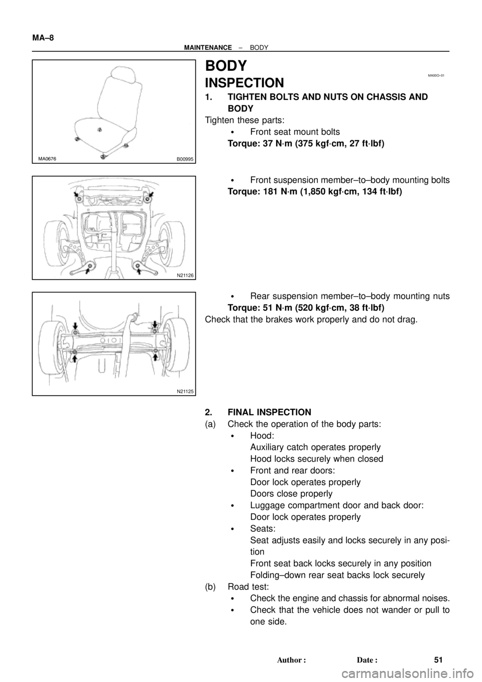
1. TIGHTEN BOLTS AND NUTS ON CHASSIS AND
BODY
Tighten these parts:
�Front seat mount bolts
Torque: 37 N´m (375 kgf´cm, 27 ft´lbf)
�Front suspension member±to±body mounting bolts
Torque: 181 N´m (1,850 kgf´cm, 134 ft´lbf)
�Rear suspension member±to±body mounting nuts
Torque: 51 N´m (520 kgf´cm, 38 ft´lbf)
Check that the brakes work properly and do not drag.
2. FINAL INSPECTION
(a) Check the operation of the body parts:
�Hood:
Auxiliary catch operates properly
Hood locks securely when closed
�Front and rear doors:
Door lock operates properly
Doors close properly
�Luggage compartment door and back door:
Door lock operates properly
�Seats:
Seat adjusts easily and locks securely in any posi-
tion
Front seat back locks securely in any position
Folding±down rear seat backs lock securely
(b) Road test:
�Check the engine and chassis for abnormal noises.
�Check that the vehicle does not wander or pull to
one side.
Page 2932 of 4592
± MAINTENANCEBODY
MA±9
52 Author�: Date�: �
Check that the brakes work properly and do not
drag.
�Do setting of the parking brake shoes and drum.
(c) Be sure to deliver a clean car. Especially check:
�Steering wheel
�Shift lever knob
�All switch knobs
�Door handles
�Seats