Page 861 of 4592
BO0L6±01
H01733
Door LockRear Door Upper
Moulding
Door Belt Moulding
Door Glass
Outside handle
Door Glass Run
Door Lock
Door Lock Striker
Rear Side Frame
Rear Door WeatherstripWindow Regulator
Inside Handle BezelInside HandleWindow
Regulator
Motor Child Protector
Lock Lever Cover
Snap Ring
Regulator
Handle Plate Door Trim Service Hole Cover Power Window
Switch Cover Door HingeDoor Hinge
Door Check w/o Power Door
Lock:
w/o Power Window:
: Specified torque
N´m (kgf´cm, ft´lbf)
3.5 (35, 31 in.´lbf)
5.5 (55, 49 in.´lbf)
5.5 (55, 49 in.´lbf)
23 (230, 17)
7.0 (70, 61 in.´lbf)
Door Lock Control Link
Door Lock Remote
Control Link
5.0 (50, 43 in.´lbf)
8.0 (80, 71 in.´lbf)
26 (260, 19)
8.0 (80, 71 in.´lbf)
30 (300, 22)
26 (260, 19)
± BODYREAR DOOR
BO±17
2365 Author�: Date�:
REAR DOOR
COMPONENTS
Page 864 of 4592

H01744
w/ Power Window:
w/o Power Window:
N20975
(b)
(b)(a )
H01746
w/o Power Door Lock
w/ Power Door Lock BO±20
± BODYREAR DOOR
2368 Author�: Date�:
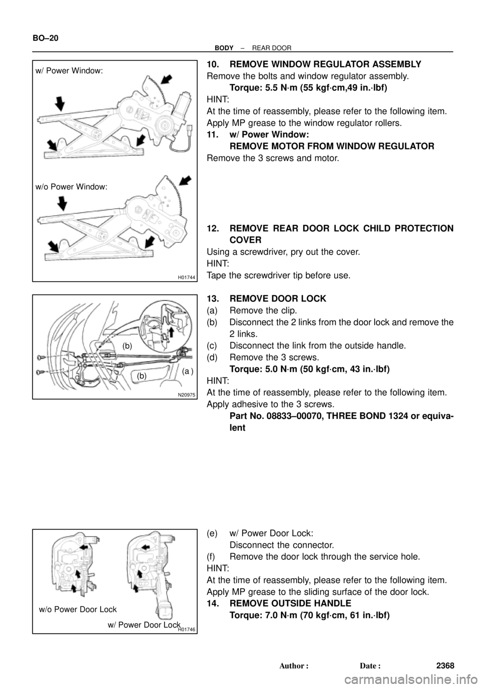
10. REMOVE WINDOW REGULATOR ASSEMBLY
Remove the bolts and window regulator assembly.
Torque: 5.5 N´m (55 kgf´cm,49 in.´lbf)
HINT:
At the time of reassembly, please refer to the following item.
Apply MP grease to the window regulator rollers.
11. w/ Power Window:
REMOVE MOTOR FROM WINDOW REGULATOR
Remove the 3 screws and motor.
12. REMOVE REAR DOOR LOCK CHILD PROTECTION
COVER
Using a screwdriver, pry out the cover.
HINT:
Tape the screwdriver tip before use.
13. REMOVE DOOR LOCK
(a) Remove the clip.
(b) Disconnect the 2 links from the door lock and remove the
2 links.
(c) Disconnect the link from the outside handle.
(d) Remove the 3 screws.
Torque: 5.0 N´m (50 kgf´cm, 43 in.´lbf)
HINT:
At the time of reassembly, please refer to the following item.
Apply adhesive to the 3 screws.
Part No. 08833±00070, THREE BOND 1324 or equiva-
lent
(e) w/ Power Door Lock:
Disconnect the connector.
(f) Remove the door lock through the service hole.
HINT:
At the time of reassembly, please refer to the following item.
Apply MP grease to the sliding surface of the door lock.
14. REMOVE OUTSIDE HANDLE
Torque: 7.0 N´m (70 kgf´cm, 61 in.´lbf)
Page 963 of 4592
BO0N5±01
H01875
Rear seatback Board
Rear Seatback frame
RH Rear Side
SeatbackRear Seatback CoverRear Seatback PadHeadrest
Support
LH Seatback Hinge Seatback Lock Knob
Seatback Lock Knob
Cover
Rear Seatback Lock
Control Cable
Rear Seatback
Control Bezel
Seat Cushion Cover LH Side Seatback Headrest
Headrest Suppot
Seatback Pad
Seatback Cover
Seat Cushion Pad
Child Restraint Seat Headrest
Rear Seatback Lock
Control
Center Seatback
Hinge
Center Seatback
Hinge
: Specified torque
N´m (kgf´cm, ft´lbf)
RH Seatback Hinge
Rear Seat center
Armrest
18 (185, 13)18 (185, 13)
18 (185, 13)Center Armrest
Hinge Cover18 (185, 13)
18 (185, 13)
7.8 (79, 69 in.´lbf)
42 (428, 31)
13 (130, 9)
17.5 (178, 12.5)
Child Restraint
Seat Coverw/ CRS: BO±118
± BODYREAR SEAT (TMMK Made)
2466 Author�: Date�:
REAR SEAT (TMMK Made)
COMPONENTS
Page 964 of 4592

BO0N6±01
± BODYREAR SEAT (TMMK Made)
BO±119
2467 Author�: Date�:
REMOVAL
1. REMOVE SEAT CUSHION ASSEMBLY
(a) Remove the seat cushion assembly.
HINT:
Remove the rear seat inner with center belt from seat cushion slit to remove the seat cushion.
(b) Remove the 2 lock hooks.
2. REMOVE LH SEATBACK ASSEMBLY
(a) Release lock to lean the seatback to front.
(b) Remove the 2 bolts and LH seatback assembly.
3. w/ CRS:
REMOVE CHILD RESTRAINT SEAT
(a) Remove child restraint seat cover.
(b) Remove the 3 bolts and 2 nuts.
Torque: 13 N´m (130 kgf´cm, 9 ft´lbf)
(c) Remove the child restraint seat.
4. w/o CRS:
REMOVE RH SEATBACK ASSEMBLY
(a) Release lock to lean the seatback to front.
(b) Remove the clips.
(c) Remove the bolts and RH seatback assembly.
5. w/ CRS:
REMOVE RH SEATBACK ASSEMBLY
(a) Remove the 3 bolts.
Torque:
RH bolt: 7.8 N´m (80 kgf´cm, 69 in.´lbf)
Center bolt: 42 N´m (428 kgf´cm, 31 ft´lbf)
(b) Remove the RH seatback assembly.
6. REMOVE LH AND RH REAR SIDE SEATBACK
(a) Remove the bolt and LH rear side seatback.
(b) Remove the bolt and RH rear side seatback.
7. REMOVE SEATBACK HINGE
(a) Remove the bolt and LH seatback hinge.
(b) Remove the 2 bolts and center seatback hinge.
Torque: 18 N´m (185 kgf´cm, 13 ft´lbf)
(c) w/o CRS:
Remove the bolt and RH seatback hinge.
Torque: 18 N´m (185 kgf´cm, 13 ft´lbf)
Page 2839 of 4592

IN04Q±03
IN±36
± INTRODUCTIONTERMS
36 Author�: Date�:
TERMS
ABBREVIATIONS USED IN THIS MANUAL
AbbreviationsMeaning
ABSAnti±Lock Brake System
ACAlternating Current
ACCAccessory
ACISAcoustic Control Induction System
ACSDAutomatic Cold Start Device
A.D.D.Automatic Disconnecting Differential
A/FAir±Fuel Ratio
AHCActive Height Control Suspension
ALRAutomatic Locking Retractor
ALTAlternator
AMPAmplifier
ANTAntenna
APPROX.Approximately
A/TAutomatic Transmission (Transaxle)
AT FAutomatic Transmission Fluid
AUTOAutomatic
AUXAuxiliary
AV GAverage
AV SAdaptive Variable Suspension
BACSBoost Altitude Compensation System
BATBattery
BDCBottom Dead Center
B/LBi±Level
B/SBore±Stroke Ratio
BTDCBefore Top Dead Center
BVSVBimetallic Vacuum Switching Valve
Calif.California
CBCircuit Breaker
CCoCatalytic Converter For Oxidation
CDCompact Disc
CFCornering Force
CGCenter Of Gravity
CHChannel
COMB.Combination
CPECoupe
CPSCombustion Pressure Sensor
CPUCentral Processing Unit
CRSChild Restraint System
CTRCenter
C/VCheck Valve
CVControl Valve
CWCurb Weight
Page 2880 of 4592

IN04Q±03
IN±34
± INTRODUCTIONTERMS
34 Author�: Date�:
TERMS
ABBREVIATIONS USED IN THIS MANUAL
AbbreviationsMeaning
ABSAnti±Lock Brake System
ACAlternating Current
ACCAccessory
ACISAcoustic Control Induction System
ACSDAutomatic Cold Start Device
A.D.D.Automatic Disconnecting Differential
A/FAir±Fuel Ratio
AHCActive Height Control Suspension
ALRAutomatic Locking Retractor
ALTAlternator
AMPAmplifier
ANTAntenna
APPROX.Approximately
A/TAutomatic Transmission (Transaxle)
AT FAutomatic Transmission Fluid
AUTOAutomatic
AUXAuxiliary
AV GAverage
AV SAdaptive Variable Suspension
BACSBoost Altitude Compensation System
BATBattery
BDCBottom Dead Center
B/LBi±Level
B/SBore±Stroke Ratio
BTDCBefore Top Dead Center
BVSVBimetallic Vacuum Switching Valve
Calif.California
CBCircuit Breaker
CCoCatalytic Converter For Oxidation
CDCompact Disc
CFCornering Force
CGCenter Of Gravity
CHChannel
COMB.Combination
CPECoupe
CPSCombustion Pressure Sensor
CPUCentral Processing Unit
CRSChild Restraint System
CTRCenter
C/VCheck Valve
CVControl Valve
CWCurb Weight
Page 3308 of 4592

SS±70
± SERVICE SPECIFICATIONSBODY
233 Author�: Date�:
Front seat inner upper track x Seat cushion1818513
Side Airbag assembly x Seatback frame1818513
Seatback assembly x Seat cushion frame6.06153 in.´lbf
Front Seat (Power Seat for TMMK Made)±±±
Side airbag assembly x Seat cushion frame6.06153 in.´lbf
Front Seat (Manual Seat for TMC Made)±±±
Side airbag assembly x Seat cushion frame6.06153 in.´lbf
Rear Seat (TMC Made)±±±
Seatback hinge x Body1818513
Rear seatback lock control x Rear seatback frame17.517812.5
Rear Seat (TMMK Made)±±±
Seatback pad (RH bolt) x Body7.87969 in.´lbf
Seatback pad (center bolt) x Body4242831
Child restraint seat x Body131309
Seatback hinge x Body1818513
Rear seatback lock control x Rear seatback frame17.517812.5
SEAT BELT±±±
Front Seat belt±±±
Shoulder anchor x Adjustable anchor4242031
Adjustable anchor x Body4242031
Inner belt x Seat4242031
Retractor x Body7.87969 in.´lbf
Floor anchor x Body4242031
Rear Seat Belt±±±
Lap outer belt anchor x Body4242031
ELR x Body4242031
Inner belt x Body4242031
Center belt x Body4242031
Page 3680 of 4592

SEAT BELT EXTENDER: '98 ± '00 ± BO002±00 January 21, 2000
Page 6 of 7
Failure to follow the recommendations indicated below could result in less effectiveness
of the seat belt restraint system in case of vehicle collision, causing personal injury.
The Seat Belt Extender must not be used:
A. By anyone other than for whom it was provided (name recorded on seat belt
extender).
B. In any vehicle and/or seat position other than the one for which it was provided.
C. When the Seat Belt Extender is provided for rear seat positions (with automatic
locking retractor), make sure the retractor is locked when in use.
If your seat belt cannot be fastened securely because it is not long enough, a
personalized seat belt extender is available from your Toyota dealer free of charge.
Please contact your local Toyota dealer so that the dealer can order the proper required
length for the extender. Bring the heaviest coat you expect to wear for proper
measurement and selection of length. Additional ordering information is available at your
Toyota dealer.
CAUTION:
When using the seat belt extender, observe the following. Failure to follow these
instructions could result in less effectiveness of the seat belt restraint system in case
of vehicle accident, increasing the chance of personal injury.
�Never use the Seat Belt Extender if you can COMFORTABLY fasten the seat belt
without it.
�The Seat Belt Extender must never be used with any child safety seats.
�Remember that the extender provided for you may not be safe when used on a
different vehicle, or for another person or at a different seating position than the
one originally intended for.
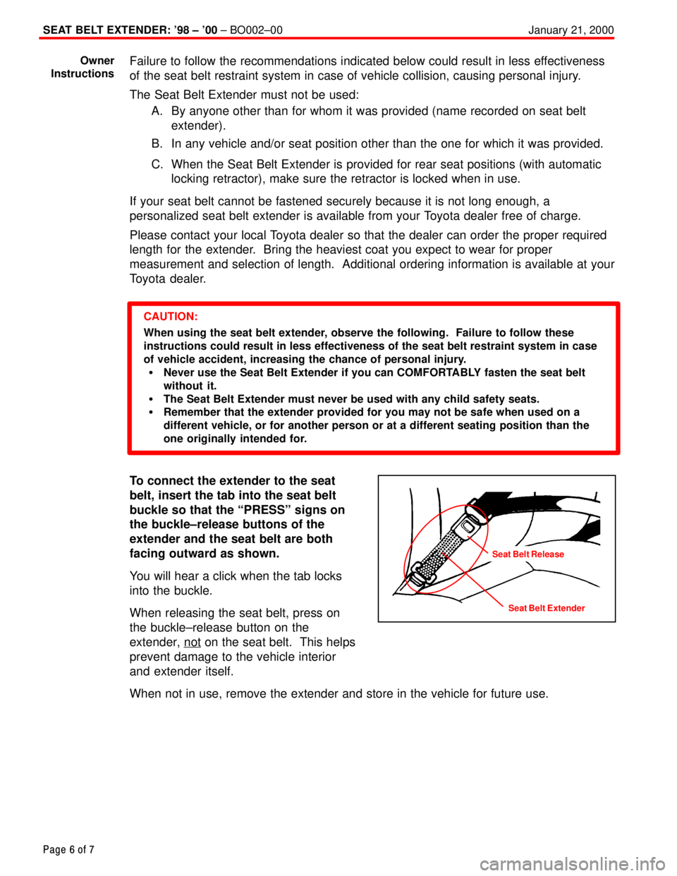
To connect the extender to the seat
belt, insert the tab into the seat belt
buckle so that the ªPRESSº signs on
the buckle±release buttons of the
extender and the seat belt are both
facing outward as shown.
You will hear a click when the tab locks
into the buckle.
When releasing the seat belt, press on
the buckle±release button on the
extender, not
on the seat belt. This helps
prevent damage to the vehicle interior
and extender itself.
When not in use, remove the extender and store in the vehicle for future use.
Owner
Instructions
Seat Belt Extender
Seat Belt Release