EM07Z±03
S05289
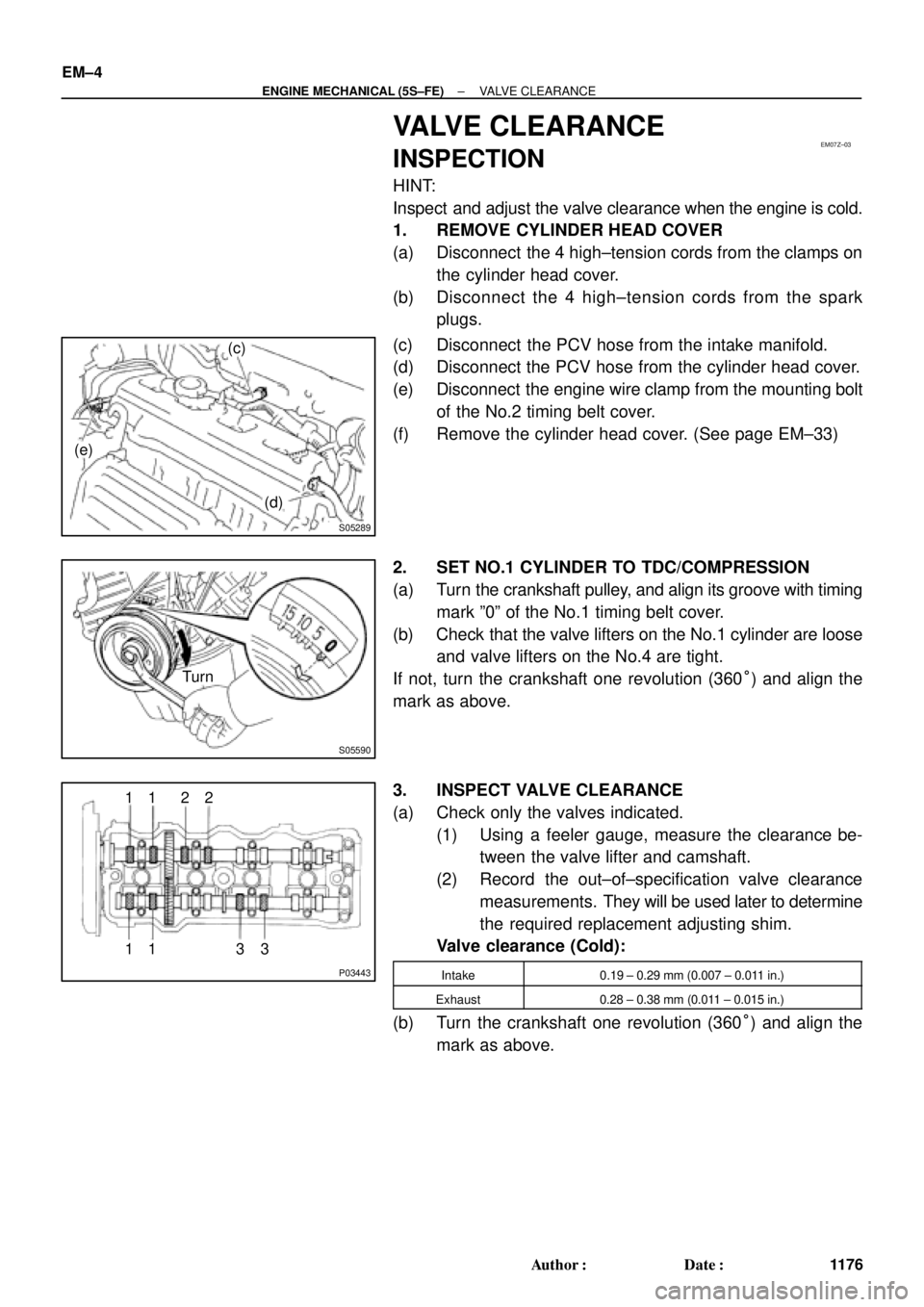
(c)
(d) (e)
S05590
Turn
P03443
1 11 122
33 EM±4
± ENGINE MECHANICAL (5S±FE)VALVE CLEARANCE
1176 Author�: Date�:
VALVE CLEARANCE
INSPECTION
HINT:
Inspect and adjust the valve clearance when the engine is cold.
1. REMOVE CYLINDER HEAD COVER
(a) Disconnect the 4 high±tension cords from the clamps on
the cylinder head cover.
(b) Disconnect the 4 high±tension cords from the spark
plugs.
(c) Disconnect the PCV hose from the intake manifold.
(d) Disconnect the PCV hose from the cylinder head cover.
(e) Disconnect the engine wire clamp from the mounting bolt
of the No.2 timing belt cover.
(f) Remove the cylinder head cover. (See page EM±33)
2. SET NO.1 CYLINDER TO TDC/COMPRESSION
(a) Turn the crankshaft pulley, and align its groove with timing
mark º0º of the No.1 timing belt cover.
(b) Check that the valve lifters on the No.1 cylinder are loose
and valve lifters on the No.4 are tight.
If not, turn the crankshaft one revolution (360°) and align the
mark as above.
3. INSPECT VALVE CLEARANCE
(a) Check only the valves indicated.
(1) Using a feeler gauge, measure the clearance be-
tween the valve lifter and camshaft.
(2) Record the out±of±specification valve clearance
measurements. They will be used later to determine
the required replacement adjusting shim.
Valve clearance (Cold):
Intake0.19 ± 0.29 mm (0.007 ± 0.011 in.)
Exhaust0.28 ± 0.38 mm (0.011 ± 0.015 in.)
(b) Turn the crankshaft one revolution (360°) and align the
mark as above.
EM04K±04
P18805
P13074
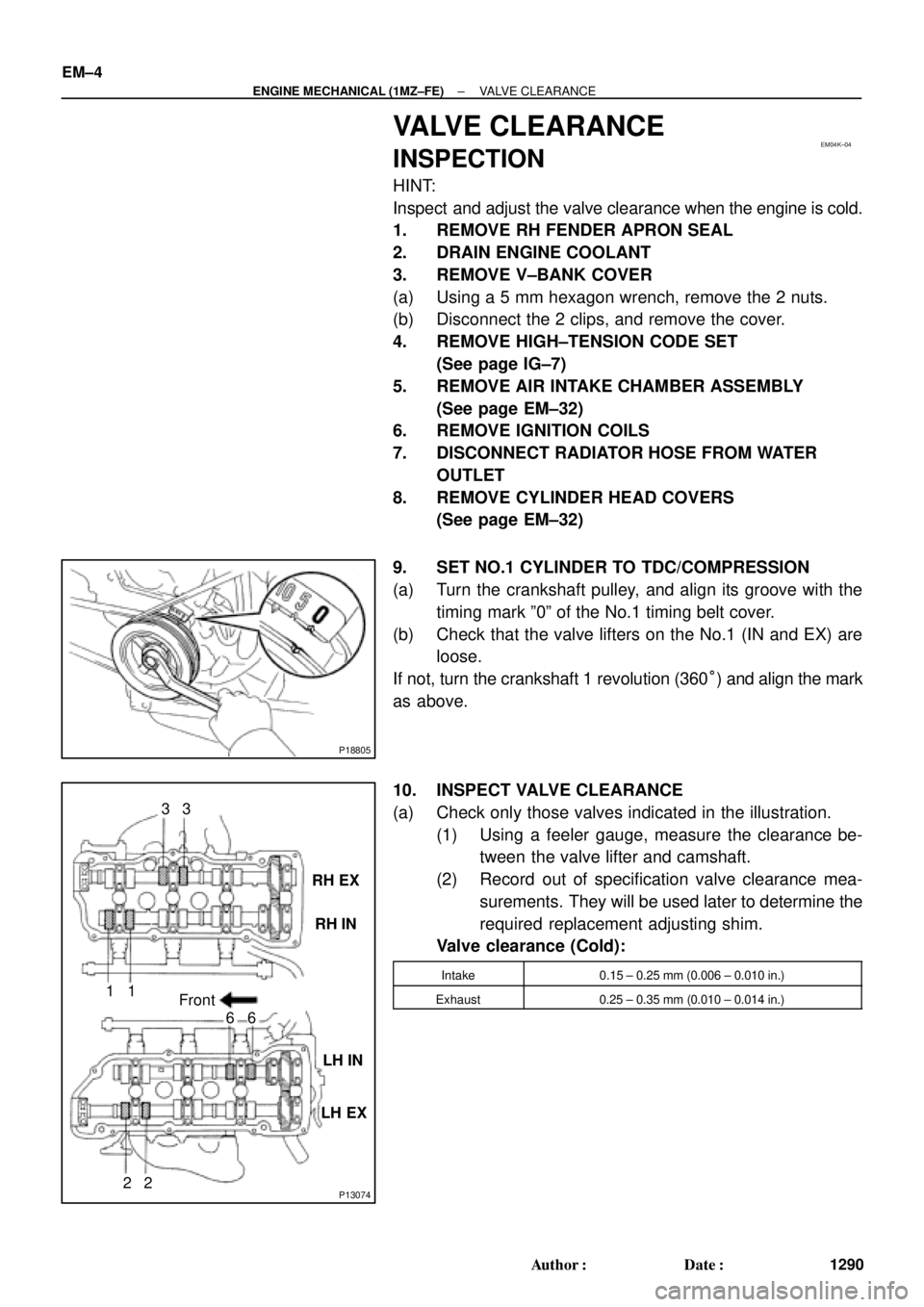
RH EX
RH IN
LH IN
LH EX 13
6
23
1
6
2Front EM±4
± ENGINE MECHANICAL (1MZ±FE)VALVE CLEARANCE
1290 Author�: Date�:
VALVE CLEARANCE
INSPECTION
HINT:
Inspect and adjust the valve clearance when the engine is cold.
1. REMOVE RH FENDER APRON SEAL
2. DRAIN ENGINE COOLANT
3. REMOVE V±BANK COVER
(a) Using a 5 mm hexagon wrench, remove the 2 nuts.
(b) Disconnect the 2 clips, and remove the cover.
4. REMOVE HIGH±TENSION CODE SET
(See page IG±7)
5. REMOVE AIR INTAKE CHAMBER ASSEMBLY
(See page EM±32)
6. REMOVE IGNITION COILS
7. DISCONNECT RADIATOR HOSE FROM WATER
OUTLET
8. REMOVE CYLINDER HEAD COVERS
(See page EM±32)
9. SET NO.1 CYLINDER TO TDC/COMPRESSION
(a) Turn the crankshaft pulley, and align its groove with the
timing mark º0º of the No.1 timing belt cover.
(b) Check that the valve lifters on the No.1 (IN and EX) are
loose.
If not, turn the crankshaft 1 revolution (360°) and align the mark
as above.
10. INSPECT VALVE CLEARANCE
(a) Check only those valves indicated in the illustration.
(1) Using a feeler gauge, measure the clearance be-
tween the valve lifter and camshaft.
(2) Record out of specification valve clearance mea-
surements. They will be used later to determine the
required replacement adjusting shim.
Valve clearance (Cold):
Intake0.15 ± 0.25 mm (0.006 ± 0.010 in.)
Exhaust0.25 ± 0.35 mm (0.010 ± 0.014 in.)