Page 1620 of 4592

643 Author�: Date�:
CIRCUIT INSPECTION
DTC")
DI1J0±01
A00414
Vehicle Speed Sensor4±Pulse 4±Pulse
Combination Meter
ECM
Transaxle
Vehicle Speed Sensor
DI±408
± DIAGNOSTICSAUTOMATIC TRANSAXLE (A140E)
643 Author�: Date�:
CIRCUIT INSPECTION
DTC P0500 Vehicle Speed Sensor Malfunction
CIRCUIT DESCRIPTION
The vehicle speed sensor outputs a 4±pulse signal for every revolution of the rotor shaft, which is rotated
by the transmission output shaft via the driven gear. After this signal is converted into a more precise rectan-
gular wave form by the wave form shaping circuit inside the combination meter, it is then transmitted to the
ECM. The ECM determines the vehicle speed based on the frequency of these pluse signals.
DTC No.DTC Detecting ConditionTrouble Area
P0500
During vehicle is being driven, no vehicle speed sensor signal
to ECM
(2 trip detection logic)�Combination meter
�Open or short in vehicle speed sensor circuit
�Vehicle speed sensor
ECM Clutch or brake slips or gear is broken�ECM
�Automatic transaxle (clutch, brake or gear etc.)
WIRING DIAGRAM
See page DI±145.
Page 1668 of 4592

691 Author�: Date�:
CIRCUIT")
DI1KB±01
A00223
Vehicle Speed
Sensor4±Pulse
Combination
Meter
ECM
Transaxle
Vehicle Speed Sensor
4±Pulse
Q00515 Q00514
DI±456
± DIAGNOSTICSAUTOMATIC TRANSAXLE (A541E)
691 Author�: Date�:
CIRCUIT INSPECTION
DTC P0500 Vehicle Speed Sensor Malfunction
CIRCUIT DESCRIPTION
The vehicle speed sensor outputs a 4±pulse signal for every revolution of the rotor shaft, which is rotated
by the transmission output shaft via the driven gear. After this signal is converted into a more precise rectan-
gular waveform by the waveform shaping circuit inside the combination meter, it is then transmitted to the
ECM. The ECM determines the vehicle speed based on the frequency of these pulse signals.
DTC No.DTC Detecting ConditionTrouble Area
P0500
No vehicle speed sensor signal to ECM under conditions (a)
and (b)
(2 trip detection logic)
(a) Park/neutral position switch is OFF
(b) Vehicle is being driven�Open or short in vehicle speed sensor circuit
�Vehicle speed sensor
�Combination meter
�ECM
At ti t l (lthb k t )Clutch or brake slips or gear is broken�Automatic transaxle (clutch, brake or gear etc.)
WIRING DIAGRAM
See page DI±333.
Page 1708 of 4592

731 Author�: Date�:
(b) Using TOYOTA hand±held tester, check the DTC.
(1) Do step 1. ~ 6. on the previo")
H07517
TOYOTA
Hand±held Tester
DLC2 DI±496
± DIAGNOSTICSANTI±LOCK BRAKE SYSTEM (DENSO Made)
731 Author�: Date�:
(b) Using TOYOTA hand±held tester, check the DTC.
(1) Do step 1. ~ 6. on the previous page.
(2) Hook up the TOYOTA hand±held tester to the
DLC2.
(3) Read the DTC by following the prompts on the tes-
ter screen.
Please refer to the TOYOTA hand±held tester oper-
ator 's manual for further details.
DTC of speed sensor check function:
Code No.DiagnosisTrouble Area
71Low output voltage of right front speed sensor
�Right front speed sensor
�Sensor installation
�Right front speed sensor rotor
72Low output voltage of left front speed sensor
�Left front speed sensor
�Sensor installation
�Left front speed sensor rotor
73Low output voltage of right rear speed sensor
�Right rear speed sensor
�Sensor installation
�Right rear speed sensor rotor
74Low output voltage of left rear speed sensor
�Left rear speed sensor
�Sensor installation
�Left rear speed sensor rotor
75Abnormal change in output voltage of right front speed sen-
sor�Right front speed sensor rotor
76Abnormal change in output voltage of left front speed
sensor�Left front speed sensor rotor
77Abnormal change in output voltage of right rear speed
sensor�Right rear speed sensor rotor
78Abnormal change in output voltage of left rear speed sensor�Left rear speed sensor rotor
Page 1709 of 4592

DI±497
732 Author�: Date�:
DIAGNOSTIC TROUBLE CODE CHART
HINT:
�Using SST 09843 ±18020, connect the terminals Tc and E1, and remove the s")
DI03D±03
± DIAGNOSTICSANTI±LOCK BRAKE SYSTEM (DENSO Made)
DI±497
732 Author�: Date�:
DIAGNOSTIC TROUBLE CODE CHART
HINT:
�Using SST 09843 ±18020, connect the terminals Tc and E1, and remove the short pin.
�If any abnormality is not found when inspection parts, inspect the ECU.
�If a malfunction code is displayed during the DTC check, check the circuit listed for the code. For details
of each code, turn to the page referred to under the ºSee pageº for respective ºDTC No.º in the DTC
chart.
DTC No.
(See Page)Detection ItemTrouble Area
11
(DI±502)Open circuit in ABS solenoid relay circuit�ABS solenoid relay
12
(DI±502)Short circuit in ABS solenoid relay circuit
�ABS solenoid relay
�ABS solenoid relay circuit
13
(DI±507)Open circuit in ABS motor relay circuit�ABS motor relay
14
(DI±507)Short circuit in ABS motor relay circuit
�ABS motor relay
�ABS motor relay circuit
21
(DI±511)Open or short circuit in 2±position solenoid circuit for right front
wheel�ABS actuator
�SFRR or SFRH circuit
22
(DI±511)Open or short circuit in 2±position solenoid circuit for left front
wheel�ABS actuator
�SFLR or SFLH circuit
23
(DI±511)Open or short circuit in 2±position solenoid circuit for right rear
wheel�ABS actuator
�SRRR or SRRH circuit
24
(DI±511)Open or short circuit in 2±position solenoid circuit for left rear
wheel�ABS actuator
�SRLR or SRLH circuit
31
(DI±514)Right front wheel speed sensor signal malfunction
32
(DI±514)Left front wheel speed sensor signal malfunction�Right front, left front, right rear and left rear speed sensor
Eh d i it33
(DI±514)Right rear wheel speed sensor signal malfunction
�Each speed sensor circuit
�Speed sensor rotor
34
(DI±514)Left rear wheel speed sensor signal malfunction
33, 34
(DI±519)Rear speed sensor rotor faulty
�Rear axle hub
�Right rear, left rear speed sensor
�Rear speed sensor circuit
41
(DI±520)Power source voltage down
�Battery
�Charging system
�Power source circuit
49
(DI±523)Open circuit in stop light switch circuit�Stop light switch
�Stop light switch circuit
51
(DI±525)Pump motor is locked�ABS pump motor
Always ON
(DI±527)Malfunction in ECU�ECU
�Battery
Page 1710 of 4592
DI03E±03
F01172
Sensor Rotor
ABS Warning Light
ABS ECU
DLC 1
Front Speed Sensor
ABS Actuator
ABS Solenoid
Relay
ABS Motor Relay
Sensor RotorFront Speed
Sensor
Stop Light SwitchDLC 2
Rear Speed Sensor DI±498
± DIAGNOSTICSANTI±LOCK BRAKE SYSTEM (DENSO Made)
733 Author�: Date�:
PARTS LOCATION
Page 1726 of 4592

749 Author�: Date�:
DTC31, 32, 33, 34Speed Sensor Circu")
BR3583
BR3582F00010
RotorSpeed Sensor
Magnet
To ECU
+V
±VHigh Speed
Low Speed
CoilNS
DI±514
± DIAGNOSTICSANTI±LOCK BRAKE SYSTEM (DENSO Made)
749 Author�: Date�:
DTC31, 32, 33, 34Speed Sensor Circuit
CIRCUIT DESCRIPTION
The speed sensor detects wheel speed and sends the ap-
propriate signals to the ECU. These signals are used to control
the ABS system. The front and rear rotors each have 48 serra-
tions.
When the rotors rotate, the magnetic field emitted by the perma-
nent magnet in the speed sensor generates an AC voltage.
Since the frequency of this AC voltage changes in direct propor-
tion to the speed of the rotor, the frequency is used by the ECU
to detect the speed of each wheel.
DTC No.DTC Detecting ConditionTrouble Area
31, 32, 33, 34
Detection of any of conditions from 1. through 4.:
1. Vehicle speed is at 10 km/h (6 mph) or more and the
speed sensor signal circuit is open or short circuit con-
tinues for 15 sec. or more.
2. Momentary interruption of the speed sensor signal oc-
curs 7 times or more.
3. Vehicle speed is at 20 km/h (12mph) or more and inter-
ference on the speed sensor signal continues for 5 sec.
or more.
4. Open circuit condition of the speed sensor signal circuit
continues for 0.5 sec. or more.
�Right front, left front, right rear, left rear speed sensor
�Each speed sensor circuit
�Speed sensor rotor
HINT:
�DTC No. 31 is for the right front speed sensor.
�DTC No. 32 is for the left front speed sensor.
�DTC No. 33 is for the right rear speed sensor.
�DTC No. 34 is for the left rear speed sensor.
Fail safe function:
If trouble occurs in the speed sensor circuit, the ECU cuts off current to the ABS solenoid relay and prohibits
ABS control.
DI1JM±02
Page 1729 of 4592
BR3795
OK NG OK NG
OK NGOK NG
W04200
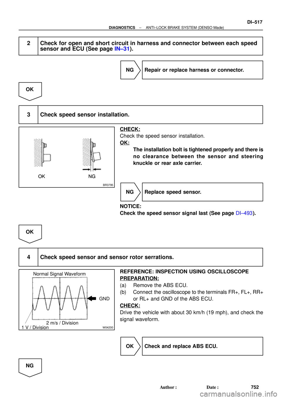
Normal Signal Waveform
1 V / Division2 m/s / DivisionGND
± DIAGNOSTICSANTI±LOCK BRAKE SYSTEM (DENSO Made)
DI±517
752 Author�: Date�:
2 Check for open and short circuit in harness and connector between each speed
sensor and ECU (See page IN±31).
NG Repair or replace harness or connector.
OK
3 Check speed sensor installation.
CHECK:
Check the speed sensor installation.
OK:
The installation bolt is tightened properly and there is
no clearance between the sensor and steering
knuckle or rear axle carrier.
NG Replace speed sensor.
NOTICE:
Check the speed sensor signal last (See page DI±493).
OK
4 Check speed sensor and sensor rotor serrations.
REFERENCE: INSPECTION USING OSCILLOSCOPE
PREPARATION:
(a) Remove the ABS ECU.
(b) Connect the oscilloscope to the terminals FR+, FL+, RR+
or RL+ and GND of the ABS ECU.
CHECK:
Drive the vehicle with about 30 km/h (19 mph), and check the
signal waveform.
OK Check and replace ABS ECU.
NG
Page 1730 of 4592
R00948
R00947
DI±518
± DIAGNOSTICSANTI±LOCK BRAKE SYSTEM (DENSO Made)
753 Author�: Date�:
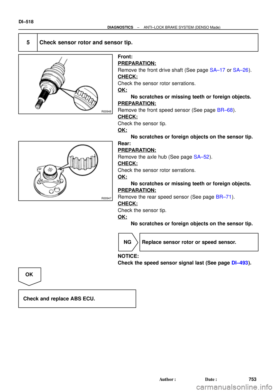
5 Check sensor rotor and sensor tip.
Front:
PREPARATION:
Remove the front drive shaft (See page SA±17 or SA±26).
CHECK:
Check the sensor rotor serrations.
OK:
No scratches or missing teeth or foreign objects.
PREPARATION:
Remove the front speed sensor (See page BR±68).
CHECK:
Check the sensor tip.
OK:
No scratches or foreign objects on the sensor tip.
Rear:
PREPARATION:
Remove the axle hub (See page SA±52).
CHECK:
Check the sensor rotor serrations.
OK:
No scratches or missing teeth or foreign objects.
PREPARATION:
Remove the rear speed sensor (See page BR±71).
CHECK:
Check the sensor tip.
OK:
No scratches or foreign objects on the sensor tip.
NG Replace sensor rotor or speed sensor.
NOTICE:
Check the speed sensor signal last (See page DI±493).
OK
Check and replace ABS ECU.