Page 1731 of 4592
± DIAGNOSTICSANTI±LOCK BRAKE SYSTEM (DENSO Made)
DI±519
754 Author�: Date�:
DTC 33, 34 Rear Speed Sensor Rotor Faulty
CIRCUIT DESCRIPTION
DTC No.DTC Detecting ConditionTrouble Area
33, 34
The condition that the both rear side wheels' speed is
lower than the front wheels' speed at 20 km/h (12 mph) or
more for 20 sec. or more when the IG switch turns ON
and OFF , which is repeated in a sequence more than 8
times.
�Rear axle hub
�Right rear, left rear speed sensor
�Rear speed sensor circuit
INSPECTION PROCEDURE
1 Check rear axle hub (See page SA±9).
NG Replace rear axle hub.
OK
2 Check rear speed sensor (See page DI±514).
NG Replace rear speed sensor.
OK
3 Check for open and short circuit in harness and connector between rear speed
sensor and ECU (See page IN±31).
NG Repair or replace harness and connector.
OK
Check and replace ABS ECU.
DI03L±03
Page 1753 of 4592

72 67
ON
OFF
0.5 sec. 0.5 sec. 0.5 sec. 0.5 sec.1.5 sec.
2.5 sec.4 sec.
Repeat
H07517
TOYOTA
Hand±held Tester
DLC2
± DIAGNOSTICSANTI±LOCK BRAKE SYSTEM")
BR3893
Malfunction Code (Example Code 72, 76)
72 67
ON
OFF
0.5 sec. 0.5 sec. 0.5 sec. 0.5 sec.1.5 sec.
2.5 sec.4 sec.
Repeat
H07517
TOYOTA
Hand±held Tester
DLC2
± DIAGNOSTICSANTI±LOCK BRAKE SYSTEM (BOSCH Made)
DI±541
776 Author�: Date�:
HINT:
�See the list of DTC shown at the bottom of this page.
�If every sensor is normal, a normal code is output (A cycle
of 0.25 sec. ON and 0.25 sec. OFF is repeated).
�If 2 or more malfunctions are indicated at the same time,
the lowest numbered code will be displayed 1st.
(12) After doing the check, disconnect the SST from ter-
minals Tc and E
1 of DLC1, and turn ignition switch
OFF.
SST 09843 ± 18020
(b) Using TOYOTA hand±held tester, check the DTC.
(1) Do step 1. ~ 6. on the previous page.
(2) Hook up the TOYOTA hand±held tester to the
DLC2.
(3) Read the DTC by following the prompts on the tes-
ter screen.
Please refer to the TOYOTA hand±held tester oper-
ator 's manual for further details.
DTC of speed sensor check function:
Code No.DiagnosisTrouble Area
71Low output voltage of right front speed sensor
�Right front speed sensor
�Sensor installation
�Right front speed sensor rotor
72Low output voltage of left front speed sensor
�Left front speed sensor
�Sensor installation
�Left front speed sensor rotor
73Low output voltage of right rear speed sensor
Right rear speed sensor
Sensor installation
Right rear speed sensor rotor
74Low output voltage of left rear speed sensor
�Left rear speed sensor
�Sensor installation
�Left rear speed sensor rotor
75Abnormal change in output voltage of right front speed
sensor�Right front speed sensor rotor
76Abnormal change in output voltage of left front speed
sensor�Left front speed sensor rotor
77Abnormal change in output voltage of right rear speed
sensor�Right rear speed sensor rotor
78Abnormal change in output voltage of left rear speed sensor�Left rear speed sensor rotor
Page 1754 of 4592

777 Author�: Date�:
DIAGNOSTIC TROUBLE CODE CHART
HINT:
�Using SST 09843 ±18020, connect the terminals Tc and E1.
�If a malfunctio")
DI03W±11
DI±542
± DIAGNOSTICSANTI±LOCK BRAKE SYSTEM (BOSCH Made)
777 Author�: Date�:
DIAGNOSTIC TROUBLE CODE CHART
HINT:
�Using SST 09843 ±18020, connect the terminals Tc and E1.
�If a malfunction code is displayed during the DTC check, check the circuit listed for the code. For details
of each code, turn to the page referred to under the ºSee pageº for respective ºDTC No.º in the DTC
chart.
DTC No.
(See Page)Detection ItemTrouble Area
11
(DI±546)ABS solenoid valve relay faulty
�ABS solenoid valve relay
�Valve supply voltage
�ECU
13
(DI±548)ABS pump motor faulty
�ABS motor relay
�Pump motor voltage
�Pump motor lead disconnected
�ECU
21
(DI±550)Right front solenoid valves faulty�ABS actuator (right front inlet or outlet solenoid valve)
22
(DI±550)Left front solenoid valves faulty�ABS actuator (left front inlet or outlet solenoid valve)
23
(DI±550)Right rear solenoid valves faulty�ABS actuator (right rear inlet or outlet solenoid valve)
24
(DI±550)Left rear solenoid valves faulty�ABS actuator (left rear inlet or outlet solenoid valve)
31
(DI±552)Right front wheel speed sensor signal malfunction
32
(DI±552)Left front wheel speed sensor signal malfunction�Right front, left front, right rear and left rear speed sensor
�Each speed sensor circuit
33
(DI±552)Right rear wheel speed sensor signal malfunction
�Each s eed sensor circuit
�Sensor installation
�ECU
34
(DI±552)Left rear wheel speed sensor signal malfunction
35
(DI±552)Open circuit in right front wheel speed sensor circuit�Right front, left front speed sensor
Eh d i it36
(DI±552)Open circuit in left front wheel speed sensor circuit
�Each speed sensor circuit
�ECU
37
(DI±557)Speed sensor rotor is wrong number of teeth on one of the 4
wheels�Speed sensor
�Sensor rotor
�ECU
38
(DI±552)Open circuit in right rear wheel speed sensor circuit�Right rear, left rear speed sensor
Eh d i it39
(DI±552)Open circuit in left rear wheel speed sensor circuit
�Each speed sensor circuit
�ECU
41
(DI±558)Low battery positive voltage
�Battery
�Charging system regulator
�Power source circuit
�ECU
58
(DI±561)Open circuit in stop light switch circuit
�Stop light switch
�Stop light switch circuit
�ECU
62
(DI±563)Malfunction in ECU�ECU
Page 1755 of 4592
DI03X±05
F01175
ABS Actuator
(w/ ECU, Relay)Front Speed Sensor
DLC1
DLC2Sensor Rotor
Rear Speed Sensor
Stop Light Switch ABS Warning Light
Sensor Rotor
Front Speed Sensor
± DIAGNOSTICSANTI±LOCK BRAKE SYSTEM (BOSCH Made)
DI±543
778 Author�: Date�:
PARTS LOCATION
Page 1764 of 4592

787 Author�: Date�:
DTC31, 32, 33, 34, 35, 36, 38, 39Sp")
BR3583
BR3582F00010
RotorSpeed Sensor
Magnet
To ECU
+V
±VHigh Speed
Low Speed
CoilNS
DI±552
± DIAGNOSTICSANTI±LOCK BRAKE SYSTEM (BOSCH Made)
787 Author�: Date�:
DTC31, 32, 33, 34, 35, 36, 38, 39Speed Sensor Circuit
CIRCUIT DESCRIPTION
The speed sensor detects wheel speed and sends the ap-
propriate signals to the ECU. These signals are used to control
the ABS system. The front and rear rotors each have 48 serra-
tions.
When the rotors rotate, the magnetic field emitted by the perma-
nent magnet in the speed sensor generates an AC voltage.
Since the frequency of this AC voltage changes in direct propor-
tion to the speed of the rotor, the frequency is used by the ECU
to detect the speed of each wheel.
DTC No.DTC Detecting ConditionTrouble Area
31, 32, 33, 34
Detection of any of conditions from 1. through 3.:
1. Vehicle speed is more than 40 km/h (25 mph), pulses
are not input for 0.01 sec.
2. After the initial start or restart and when the vehicle
speed has reached 12 km/h (7 mph), the wheel with 0
km/h (0 mph) of wheel speed is detected.
3. After the initial start or restart and when the vehicle
speed has reached 70 km/h (44 mph), front wheel with 0
km/h (0 mph) of wheel speed is detected.
�Right front, left front, right rear, left rear speed sensor
�Each speed sensor circuit
�Sensor installation
�ECU
35, 36, 38, 39Detecting abnormality in the resistance value of each speed
sensor.�Right front, left front, right rear, left rear speed sensor
�Each speed sensor circuit
�ECU
HINT:
�DTC No. 31 and 35 are for the right front speed sensor.
�DTC No. 32 and 36 are for the left front speed sensor.
�DTC No. 33 and 38 are for the right rear speed sensor.
�DTC No. 34 and 39 are for the left rear speed sensor.
Fail safe function:
If trouble occurs in the speed sensor circuit, the ECU cuts off current to the ABS solenoid valve relay and
prohibits ABS control.
DI043±04
Page 1767 of 4592
BR3795
OK NG OK NG
OK NGOK NG
R00948
± DIAGNOSTICSANTI±LOCK BRAKE SYSTEM (BOSCH Made)
DI±555
790 Author�: Date�:
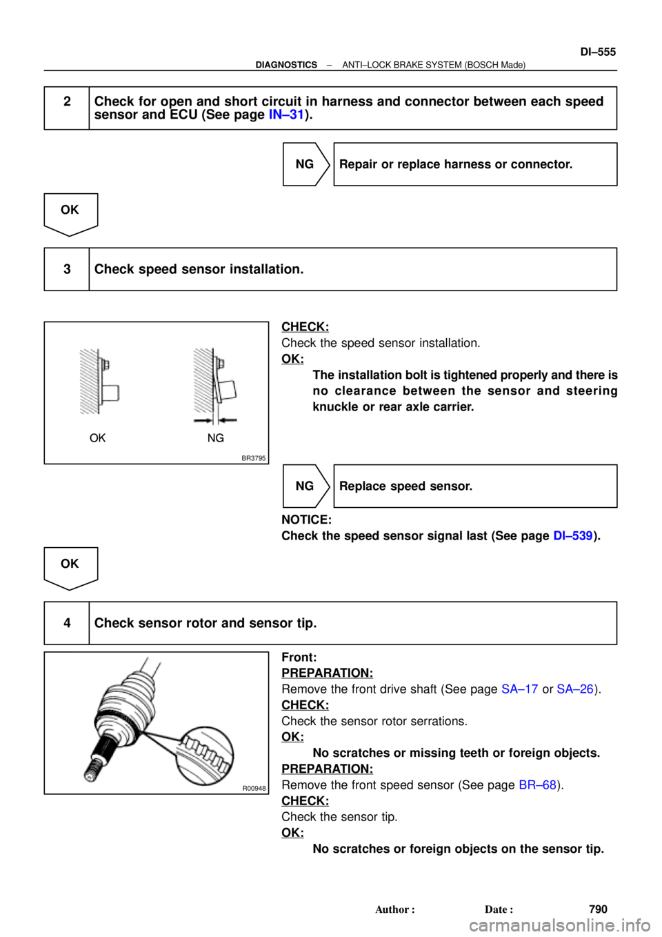
2 Check for open and short circuit in harness and connector between each speed
sensor and ECU (See page IN±31).
NG Repair or replace harness or connector.
OK
3 Check speed sensor installation.
CHECK:
Check the speed sensor installation.
OK:
The installation bolt is tightened properly and there is
no clearance between the sensor and steering
knuckle or rear axle carrier.
NG Replace speed sensor.
NOTICE:
Check the speed sensor signal last (See page DI±539).
OK
4 Check sensor rotor and sensor tip.
Front:
PREPARATION:
Remove the front drive shaft (See page SA±17 or SA±26).
CHECK:
Check the sensor rotor serrations.
OK:
No scratches or missing teeth or foreign objects.
PREPARATION:
Remove the front speed sensor (See page BR±68).
CHECK:
Check the sensor tip.
OK:
No scratches or foreign objects on the sensor tip.
Page 1768 of 4592
R00947
DI±556
± DIAGNOSTICSANTI±LOCK BRAKE SYSTEM (BOSCH Made)
791 Author�: Date�:
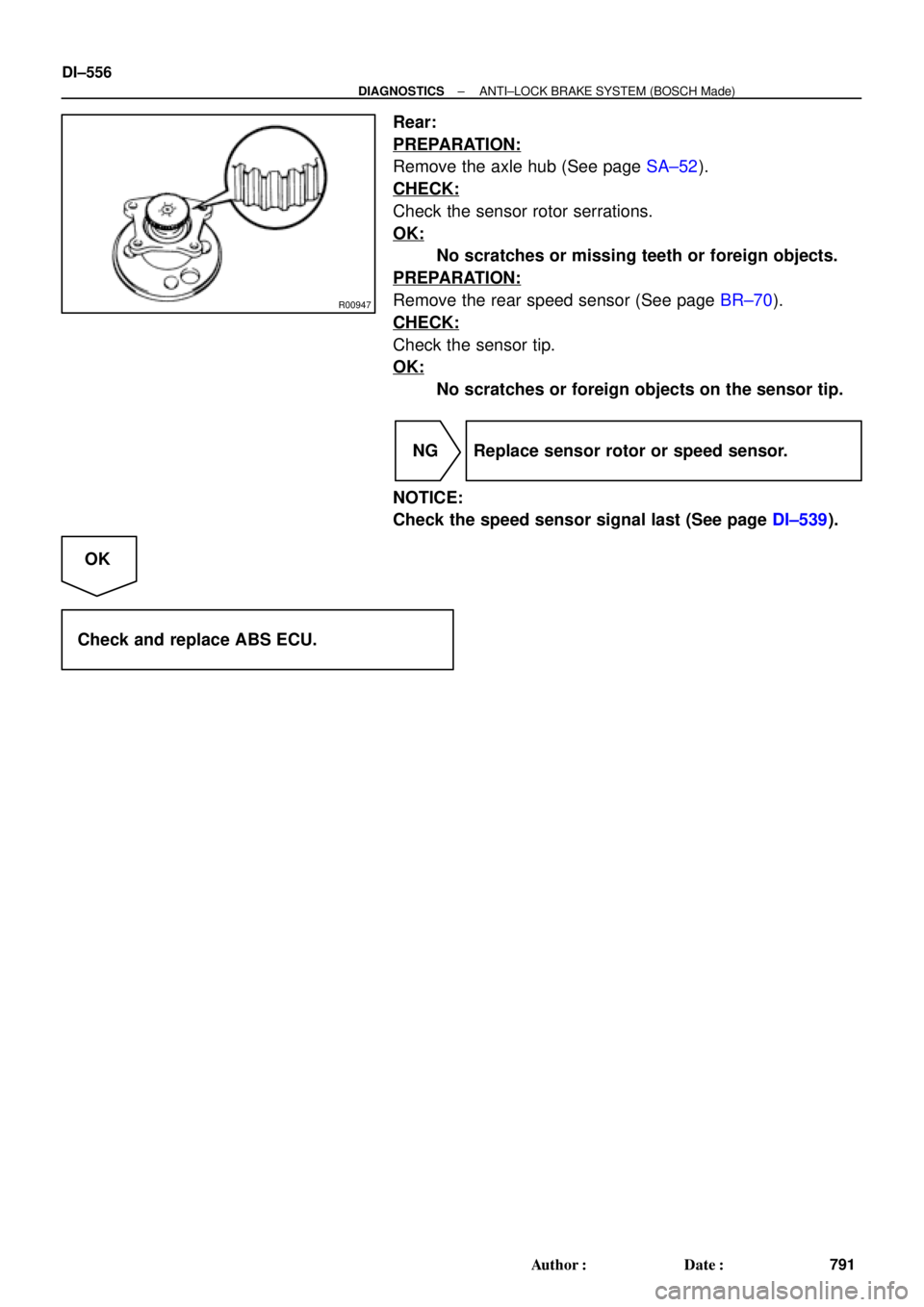
Rear:
PREPARATION:
Remove the axle hub (See page SA±52).
CHECK:
Check the sensor rotor serrations.
OK:
No scratches or missing teeth or foreign objects.
PREPARATION:
Remove the rear speed sensor (See page BR±70).
CHECK:
Check the sensor tip.
OK:
No scratches or foreign objects on the sensor tip.
NG Replace sensor rotor or speed sensor.
NOTICE:
Check the speed sensor signal last (See page DI±539).
OK
Check and replace ABS ECU.
Page 1769 of 4592

DI±557
792 Author�: Date�:
DTC 37 Speed Sensor Rotor Faulty
CIRCUIT DESCRIPTION
DTC No.DTC Detecting ConditionTrouble Area
37
Detection of any of co")
± DIAGNOSTICSANTI±LOCK BRAKE SYSTEM (BOSCH Made)
DI±557
792 Author�: Date�:
DTC 37 Speed Sensor Rotor Faulty
CIRCUIT DESCRIPTION
DTC No.DTC Detecting ConditionTrouble Area
37
Detection of any of conditions from 1. through 3.:
1. Occurrence of differential to some degree in the wheel
speed between the front and rear wheels of either left or
right side of the vehicle and the front left and right
wheels. (Detection of differential in mini tire size, spin-
ning wheel and decelerating wheel.)
2. Continuous ABS control for 60 sec. or more.
3. Interference on 1 or more wheels for 20 sec. with the
brake pedal depressed, or for 5 sec. when the brake
pedal is not depressed.
�Speed sensor
�Sensor rotor
�ECU
INSPECTION PROCEDURE
1 Check sensor rotor (See page DI±552).
NG Replace sensor rotor.
OK
2 Check speed sensor (See page DI±552).
NG Replace speed sensor.
OK
3 Check for open and short circuit in harness and connector between speed sen-
sor and ECU (See page IN±31).
NG Repair or replace harness and connector.
OK
Check and replace ABS ECU.
DI044±04

Front Speed Sensor
DLC1
DLC2Sensor Rotor
Rear Speed Sensor
Stop Light Switch ABS Warning Light
Sensor Rotor
Front Speed Sensor
± DIAGNOSTICSANTI±LOCK BRA")