Page 2355 of 4592
± DIAGNOSTICSANTI±LOCK BRAKE SYSTEM
DI±203
DTC 33, 34 Rear Speed Sensor Rotor Faulty
CIRCUIT DESCRIPTION
DTC No.DTC Detecting ConditionTrouble Area
33, 34
The condition that the both rear side wheels' speed is
lower than the front wheels' speed at 20 km/h (12 mph) or
more for 20 sec. or more when the IG switch turns ON
and OFF , which is repeated in a sequence more than 8
times.
�Rear axle hub
�Right rear, left rear speed sensor
�Rear speed sensor circuit
INSPECTION PROCEDURE
1 Check rear axle hub (See Pub. No. RM654U on page SA±52).
NG Replace rear axle hub.
OK
2 Check rear speed sensor (See page DI±198).
NG Replace rear speed sensor.
OK
3 Check for open and short circuit in harness and connector between rear speed
sensor and ECU (See page IN±29).
NG Repair or replace harness and connector.
OK
Check and replace ABS ECU.
DI03L±04
Page 2483 of 4592

I00281
Cruise Control ECU
C16
G±B
2 1 34W±B
3
STOP Fuse8 Stop Light Switch
4
R±Y
Stop Lights Cruise Control Actuator
� Actuator Magnetic Clutch
J6
J6AAJ/C
W±B
1J
1J
W±B
A
J/C
IF 8
7
J9Instrument
Panel J/BL
± DIAGNOSTICSCRUISE CONTROL SYSTEM
DI±331
DTC 12 Actuator Magnetic Clutch Circuit
CIRCUIT DESCRIPTION
This circuit turns on the magnetic clutch inside the actuator during cruise control operation according to the
signal from the ECU. If a malfunction occurs in the actuator or speed sensor, etc. during cruise control opera-
tion, the rotor shaft between the motor and control plate is released.
When the brake pedal is depressed, the stop light switch turns on, supplying electrical power to the stop light.
Power supply to the magnetic clutch is mechanically cut and the magnetic clutch is turned OFF.
When driving downhill, if the vehicle speed exceeds the set speed by 15 km/h (9 mph), the ECU turns the
safety magnet clutch OFF. If the vehicle speed later drops to within 10 km/h (6 mph), cruise control at the
set speed is resumed.
DTC No.DTC Detecting ConditionTrouble Area
12Short in actuator magnetic clutch circuit.
Open (0.8 sec.) in actuator magnetic clutch circuit.
�STOP Fuse
�Stop light switch
�Actuator magnetic clutch
�Harness or connector between cruise control ECU and
actuator magnetic clutch, actuator magnetic clutch and body
ground
�Cruise control ECU
WIRING DIAGRAM
DI08N±13
Page 3634 of 4592

SA1JR±01
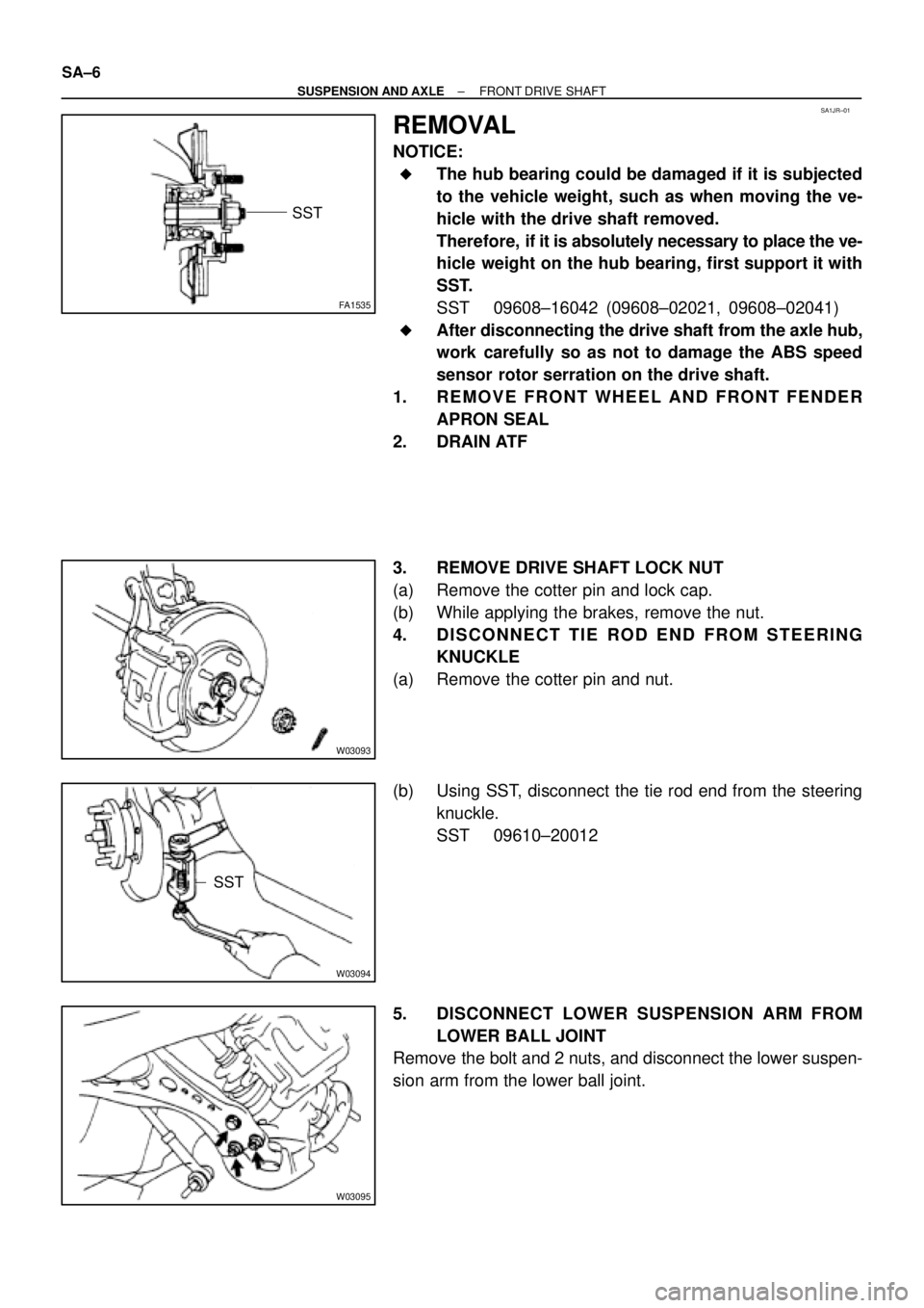
FA1535
SST
W03093
W03094
SST
W03095
SA±6
± SUSPENSION AND AXLEFRONT DRIVE SHAFT
REMOVAL
NOTICE:
�The hub bearing could be damaged if it is subjected
to the vehicle weight, such as when moving the ve-
hicle with the drive shaft removed.
Therefore, if it is absolutely necessary to place the ve-
hicle weight on the hub bearing, first support it with
SST.
SST 09608±16042 (09608±02021, 09608±02041)
�After disconnecting the drive shaft from the axle hub,
work carefully so as not to damage the ABS speed
sensor rotor serration on the drive shaft.
1. REMOVE FRONT WHEEL AND FRONT FENDER
APRON SEAL
2. DRAIN ATF
3. REMOVE DRIVE SHAFT LOCK NUT
(a) Remove the cotter pin and lock cap.
(b) While applying the brakes, remove the nut.
4. DISCONNECT TIE ROD END FROM STEERING
KNUCKLE
(a) Remove the cotter pin and nut.
(b) Using SST, disconnect the tie rod end from the steering
knuckle.
SST 09610±20012
5. DISCONNECT LOWER SUSPENSION ARM FROM
LOWER BALL JOINT
Remove the bolt and 2 nuts, and disconnect the lower suspen-
sion arm from the lower ball joint.
Page 3642 of 4592

SA1EC±02
SA±14
± SUSPENSION AND AXLEFRONT DRIVE SHAFT
INSTALLATION
1. LH drive shaft:
INSTALL DRIVE SHAFT TO TRANSAXLE
(a) Install a new snap ring to the inboard joint shaft.
(b) Coat the gear oil to the inboard joint shaft and differential case sliding surface.
(c) Set the snap ring with opening side facing downward.
(d) Using a brass bar and hammer, install the drive shaft.
NOTICE:
Be careful not to damage the dust cover of the drive shaft and oil seal lip of the transaxle.
HINT:
Whether the inboard joint shaft is in contact with the pinion shaft or not can be known from the sound or feel-
ing when driving it in.
(e) Check that there is 2 ± 3 mm (0.08 ± 0.12 in.) of play in the axial direction.
(f) Check that the drive shaft cannot be removed by hand.
2. RH drive shaft:
INSTALL DRIVE SHAFT TO TRANSAXLE
(a) Install the drive shaft.
NOTICE:
Be careful not to damage the dust cover of the drive shaft and oil seal lip of the transaxle.
(b) Using pliers, install a new snap ring.
(c) Install a new bearing lock bolt.
Torque: 32 N´m (330 kgf´cm, 24 ft´lbf)
3. CONNECT DRIVE SHAFT TO AXLE HUB
NOTICE:
Be careful not to damage the boot and ABS speed sensor rotor.
4. CONNECT LOWER SUSPENSION ARM TO LOWER BALL JOINT
Torque: 127 N´m (1,300 kgf´cm, 94 ft´lbf)
5. CONNECT TIE ROD END TO STEERING KNUCKLE
(a) Connect the tie rod end to the steering knuckle.
(b) Install the nut and a new cotter pin.
If the holes for the cotter pin are not aligned, tighten the nut further up to 60°.
Torque: 49 N´m (500 kgf´cm, 36 ft´lbf)
6. INSTALL DRIVE SHAFT LOCK NUT
(a) While applying brakes, install the nut.
Torque: 294 N´m (3,000 kgf´cm, 217 ft´lbf)
(b) Install the lock cap and a new cotter pin.
If the holes for the cotter pin are not aligned, tighten the nut further up to 60°.
7. FILL AND CHECK ATF (See page DI±133)
8. INSTALL FRONT FENDER APRON SEAL
9. INSTALL FRONT WHEEL
Torque: 103 N´m (1,050 kgf´cm, 76 ft´lbf)
10. CHECK FRONT WHEEL ALIGNMENT (See page SA±1)
11. CHECK ABS SPEED SENSOR SIGNAL (See page DI±177)
Page 3753 of 4592
BRAKES
BK91-001
MARCH 15, 1991
ALL MODELS
Printed on Recycled Paper.
TOYOTA MOTOR SALES U.S.A., INC.
BRAKE DISC ANTI±RUST COVER REMOVALPage 1 of 2
During the removal of the Anti±Rust Covers, do not use screwdrivers or other sharp objects. The
use of such tools may result in the scratching of the outer rotor surface.
Step±by±step instructions for removing the Anti±Rust Covers are provided on the following page.
Page 3755 of 4592

Toyota Supports ASE CertificationPage 1 of 1
BR001±99
Title:
FRONT BRAKE NOISE
Models:
'97±'99 V±6 Camry and '98±'99 Avalon
Technical Service
BULLETIN
April 23, 1999
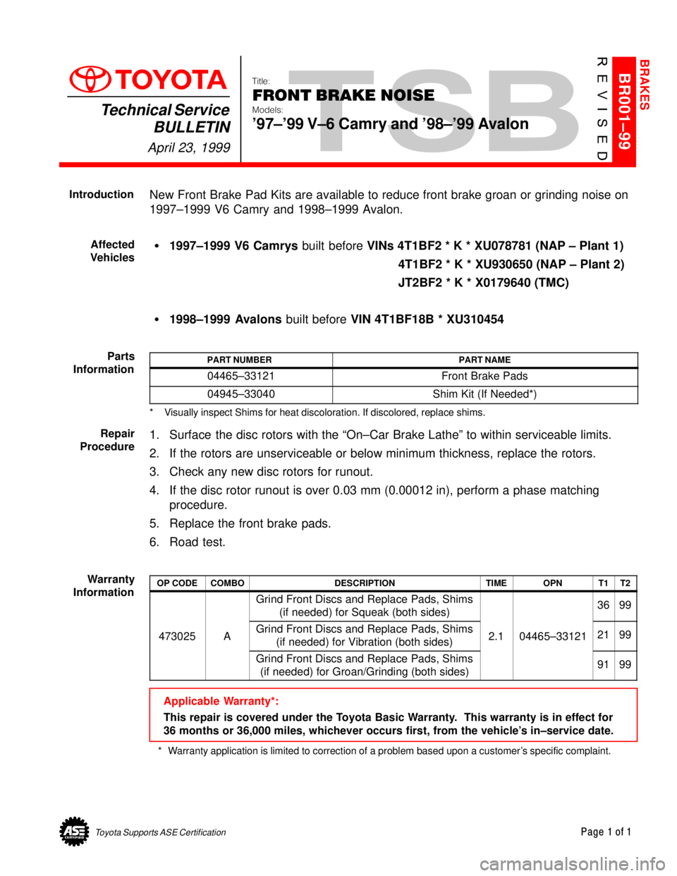
New Front Brake Pad Kits are available to reduce front brake groan or grinding noise on
1997±1999 V6 Camry and 1998±1999 Avalon.
�1997±1999 V6 Camrys built before VINs 4T1BF2 * K * XU078781 (NAP ± Plant 1)
4T1BF2 * K * XU930650 (NAP ± Plant 2)
JT2BF2 * K * X0179640 (TMC)
�1998±1999 Avalons built before VIN 4T1BF18B * XU310454
PART NUMBERPART NAME
04465±33121Front Brake Pads
04945±33040Shim Kit (If Needed*)
* Visually inspect Shims for heat discoloration. If discolored, replace shims.
1. Surface the disc rotors with the ªOn±Car Brake Latheº to within serviceable limits.
2. If the rotors are unserviceable or below minimum thickness, replace the rotors.
3. Check any new disc rotors for runout.
4. If the disc rotor runout is over 0.03 mm (0.00012 in), perform a phase matching
procedure.
5. Replace the front brake pads.
6. Road test.
OP CODECOMBODESCRIPTIONTIMEOPNT1T2
Grind Front Discs and Replace Pads, Shims
(if needed) for Squeak (both sides)3699
473025AGrind Front Discs and Replace Pads, Shims
(if needed) for Vibration (both sides)2.104465±331212199
Grind Front Discs and Replace Pads, Shims
(if needed) for Groan/Grinding (both sides)9199
Applicable Warranty*:
This repair is covered under the Toyota Basic Warranty. This warranty is in effect for
36 months or 36,000 miles, whichever occurs first, from the vehicle's in±service date.
* Warranty application is limited to correction of a problem based upon a customer's specific complaint.
BRAKES
Introduction
Affected
Vehicles
Parts
Information
Repair
Procedure
Warranty
Information
Page 3756 of 4592
TOYOTA MOTOR SALES U.S.A., INC.
This TSB outlines the causes of brake vibration and pulsation, as well as the best corrective
measures to use.
CONTENTS
1) Symptoms of brake vibration and pulsation
2) Cause of vibration/pulsation problems
3) Advantages of using an on±car brake lathe
4) Rotor replacement and off±car brake lathe procedure
1) SYMPTOMS OF BRAKE VIBRATION AND PULSATION
Brake vibration problems generally involve one or both of two phenomena: body vibration and/
or pedal pulsation.
A. BRAKE VIBRATION
Applying brakes causes vibration to occur in the instrument panel, steering column, steering
wheel, and/or body of the vehicle (See Figure 1 below).
BRAKE VIBRATION AND/OR PULSATIONPage 1 of 6
BRAKES
BR94±002
FEBRUARY 7, 1994
ALL MODELS
Figure 1
Page 3757 of 4592
BR002±94
BRAKE VIBRATION AND/OR PULSATIONPage 2 of 6
B. PEDAL PULSATION
Applying brakes causes the brake pedal to pulsate. This brake pulsation sometimes
causes the steering wheel to oscillate when the brakes are applied (See Figure 2 below).
2) CAUSE OF VIBRATION/PULSATION PROBLEMS
Brake rotor thickness variation causes brake vibration due to changes in the braking force as
thick/thin portions of the rotor pass the pads. Brake rotor thickness variation can be measured
with a micrometer as shown in Figure 3 below.
Figure 2
10 mm
Divide Into
8 Equal Parts & Measure
at each location
Thickness Variation = Maximum ± Minimum
Figure 3