Page 3758 of 4592

BR002±94
BRAKE VIBRATION AND/OR PULSATIONPage 3 of 6
There are two factors which cause excessive rotor thickness variation:
A. ROTOR RUNOUT
±Rotor runout can be caused by poor mating of flanges between the hub and rotor when
assembled as a unit. Manufacturing tolerance stack±up of the rotor and hub may also
cause excessive rotor assembly runout (See Figure 4 below).
± If there is rotor runout, a portion of the rotor comes into contact with the brake pad on
each rotor revolution. If left like this, the portion of the rotor that contacts the brake pad
becomes worn, creating thickness variation.
B. EXCESSIVE RUST OR CORROSION ON ROTOR SURFACE
± Driving in areas where salt is applied to road surfaces for winter conditions can cause
rust and corrosion when the vehicle is parked for an extended period of time. This occurs
on the area where the brake pads are not in contact with the rotor.
± When a vehicle is driven with rusted rotors, the area with corrosion wears at a
different rate than the non±corroded areas, resulting in excessive thickness variation.
Thickness Variation = A ± B
RunoutA
B
Figure 4
Page 3759 of 4592

BR002±94
BRAKE VIBRATION AND/OR PULSATIONPage 4 of 6
3) Advantages Of Using An On±Car Brake Lathe
Toyota Motor Corporation Engineers strongly recommend that an on±car brake lathe be used
for repairing brake vibration and pulsation. This method improves rotor and hub combined
runout, and is the preferred method when compared to rotor replacement and off±the±car rotor
machining.
A. Technical Advantage of Caliper Mounted Brake Lathe
± Installing the brake lathe in the same position as the caliper results in minimal runout
relative to the caliper.
± Eliminating this runout minimizes the pad grinding on the rotor and reduces rotor
thickness variation.
B. Practical Use Benefits
± Resurfacing rotors on vehicles with rotor/hub assemblies can be performed easily.
± Vehicles with corrosion between hub and rotor flanges can be machined without
removing rotor from hub.
4) Rotor Replacement And Off±Car Brake Lathe Procedures
If an on±car brake lathe is not available at your dealership, it may be necessary to use an off±car
lathe or replace rotors. In order to ensure proper brake vibration and pulsation repairs, pay close
attention to the following precautions:
A. Off±Car Brake Lathe Precautions
± Perform routine maintenance of brake lathe components (clearance of arbor shaft to
adapters may need to be repaired).
± Clean all adapters and shaft to maintain accuracy of equipment.
± When installing rotor to machine, clean mud, rust, and/or foreign material from the
adapters and rotors.
± After installing rotor on machine, check rotor runout using dial indicator. If runout is
excessive, determine the cause and correct it.
± Follow lathe manufacturer repair procedures. Do not cut excessive amounts off rotor
during the first cut to save time.
Anytime a rotor is machined it must be measured for minimum rotor thickness. The
thickness for the rotor is never to be less than minimum thickness as specified in the
appropriate repair manual.
Page 3760 of 4592
BR002±94
BRAKE VIBRATION AND/OR PULSATIONPage 5 of 6
B. Installation of Rotor
± Check wheel bearing pre±load. If excessive movement is found, adjust bearing
pre±load.
± Using a dial indicator, measure the rotor 10 mm from the outside edge
(See Figure 5 below).
Figure 5
Page 3761 of 4592
BR002±94
BRAKE VIBRATION AND/OR PULSATIONPage 6 of 6
C. Phase Match Rotor To Hub
± If rotor runout is at the maximum value or greater, (refer to appropriate repair manual)
index the rotor one lug and measure the runout again. Repeat this process, moving the
rotor one lug each time, until the position is found where the runout is at the minimum and
within the maximum value listed in the appropriate repair manual
(See Figure 6 below).
± Tighten lug nuts to the specified torque following a star sequence when installing wheel
(See Figure 7 below).
Note: DO NOT USE AIR IMPACT WRENCH.
Four Holes Five Holes
Figure 7Figure 6
Page 3764 of 4592

BRAKE PAD CLICKING NOISE ± BR004±00 October 20, 2000
Page 2 of 4
There are two types of brake calipers: floating and fixed. Check the type of brake caliper
installed on the vehicle by removing the wheel assembly.
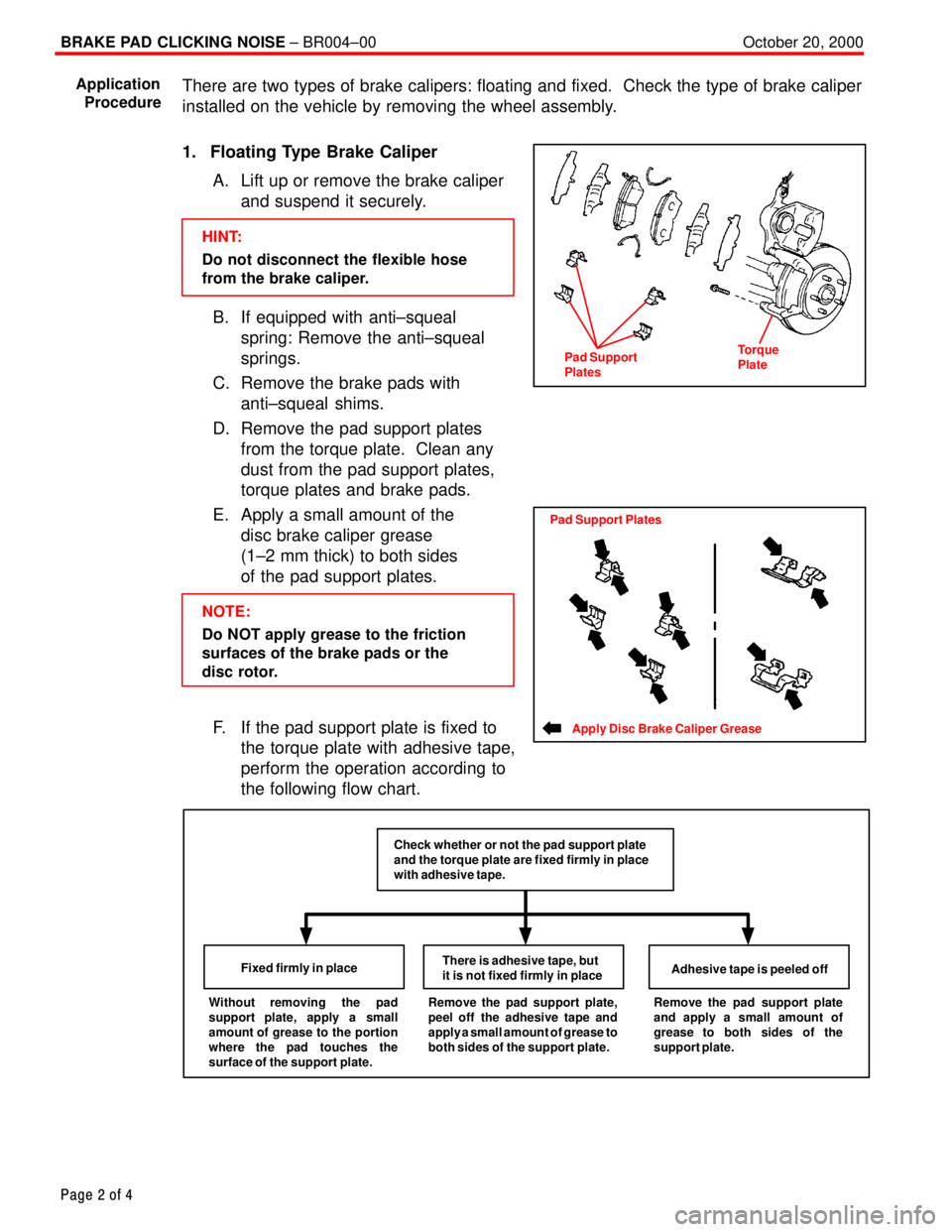
1. Floating Type Brake Caliper
A. Lift up or remove the brake caliper
and suspend it securely.
HINT:
Do not disconnect the flexible hose
from the brake caliper.
B. If equipped with anti±squeal
spring: Remove the anti±squeal
springs.
C. Remove the brake pads with
anti±squeal shims.
D. Remove the pad support plates
from the torque plate. Clean any
dust from the pad support plates,
torque plates and brake pads.
E. Apply a small amount of the
disc brake caliper grease
(1±2 mm thick) to both sides
of the pad support plates.
NOTE:
Do NOT apply grease to the friction
surfaces of the brake pads or the
disc rotor.
F. If the pad support plate is fixed to
the torque plate with adhesive tape,
perform the operation according to
the following flow chart.
Without removing the pad
support plate, apply a small
amount of grease to the portion
where the pad touches the
surface of the support plate.Fixed firmly in placeThere is adhesive tape, but
it is not fixed firmly in placeAdhesive tape is peeled offRemove the pad support plate,
peel off the adhesive tape and
apply a small amount of grease to
both sides of the support plate.Remove the pad support plate
and apply a small amount of
grease to both sides of the
support plate.
Check whether or not the pad support plate
and the torque plate are fixed firmly in place
with adhesive tape.
Application
Procedure
Pad Support
PlatesTorque
Plate
Apply Disc Brake Caliper Grease
Pad Support Plates
Page 3765 of 4592

BRAKE PAD CLICKING NOISE ± BR004±00 October 20, 2000
Page 3 of 4
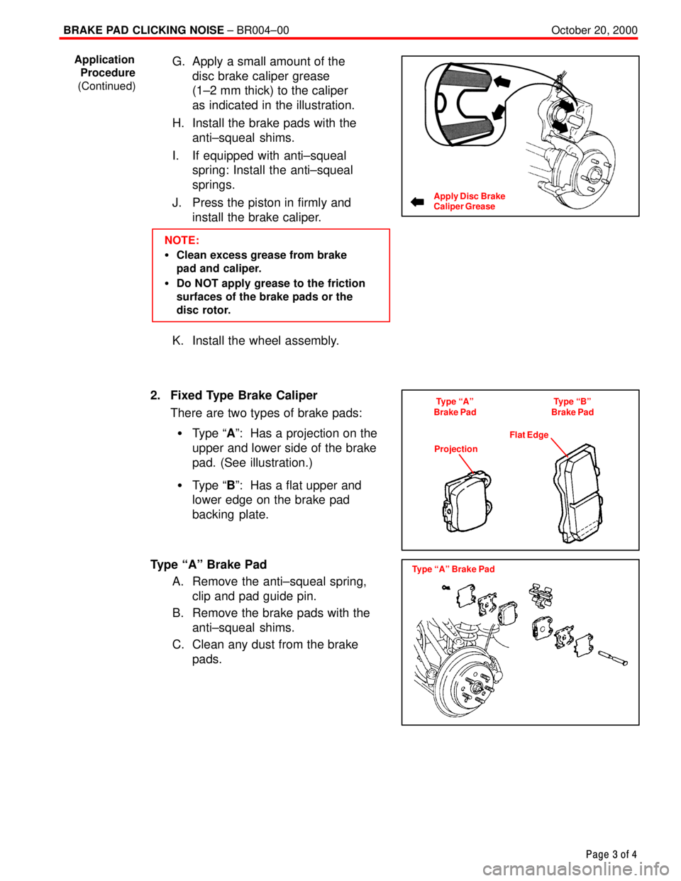
G. Apply a small amount of the
disc brake caliper grease
(1±2 mm thick) to the caliper
as indicated in the illustration.
H. Install the brake pads with the
anti±squeal shims.
I. If equipped with anti±squeal
spring: Install the anti±squeal
springs.
J. Press the piston in firmly and
install the brake caliper.
NOTE:
�Clean excess grease from brake
pad and caliper.
�Do NOT apply grease to the friction
surfaces of the brake pads or the
disc rotor.
K. Install the wheel assembly.
2. Fixed Type Brake Caliper
There are two types of brake pads:
�Type ªAº: Has a projection on the
upper and lower side of the brake
pad. (See illustration.)
�Type ªBº: Has a flat upper and
lower edge on the brake pad
backing plate.
Type ªAº Brake Pad
A. Remove the anti±squeal spring,
clip and pad guide pin.
B. Remove the brake pads with the
anti±squeal shims.
C. Clean any dust from the brake
pads.
Application
Procedure
(Continued)
Apply Disc Brake
Caliper Grease
Type ªAº
Brake PadType ªBº
Brake Pad
ProjectionFlat Edge
Type ªAº Brake Pad
Page 3766 of 4592

BRAKE PAD CLICKING NOISE ± BR004±00 October 20, 2000
Page 4 of 4
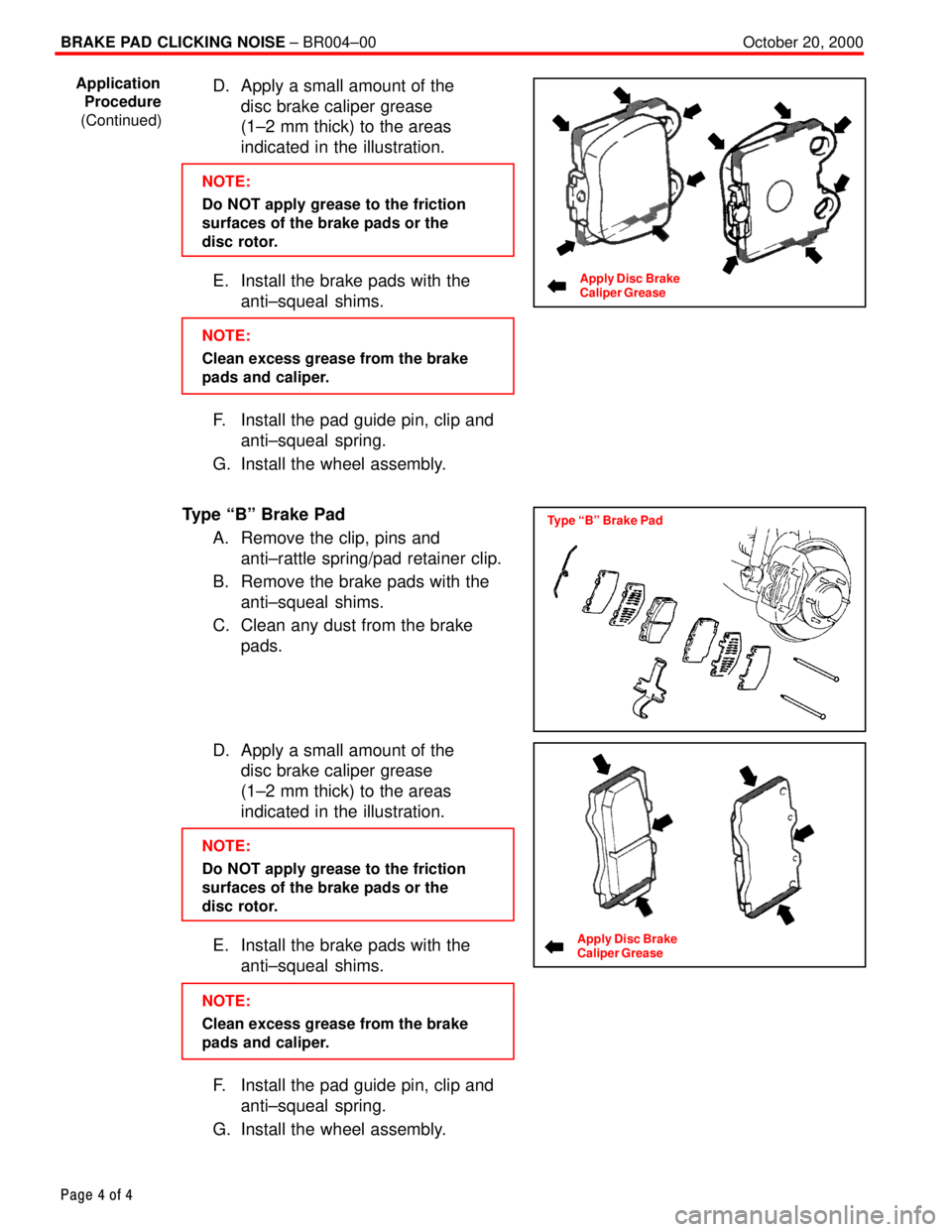
D. Apply a small amount of the
disc brake caliper grease
(1±2 mm thick) to the areas
indicated in the illustration.
NOTE:
Do NOT apply grease to the friction
surfaces of the brake pads or the
disc rotor.
E. Install the brake pads with the
anti±squeal shims.
NOTE:
Clean excess grease from the brake
pads and caliper.
F. Install the pad guide pin, clip and
anti±squeal spring.
G. Install the wheel assembly.
Type ªBº Brake Pad
A. Remove the clip, pins and
anti±rattle spring/pad retainer clip.
B. Remove the brake pads with the
anti±squeal shims.
C. Clean any dust from the brake
pads.
D. Apply a small amount of the
disc brake caliper grease
(1±2 mm thick) to the areas
indicated in the illustration.
NOTE:
Do NOT apply grease to the friction
surfaces of the brake pads or the
disc rotor.
E. Install the brake pads with the
anti±squeal shims.
NOTE:
Clean excess grease from the brake
pads and caliper.
F. Install the pad guide pin, clip and
anti±squeal spring.
G. Install the wheel assembly.
Application
Procedure
(Continued)
Apply Disc Brake
Caliper Grease
Type ªBº Brake Pad
Apply Disc Brake
Caliper Grease