Page 2881 of 4592

± INTRODUCTIONTERMS
IN±35
35 Author�: Date�:
DCDirect Current
DEFDefogger
DFLDeflector
DIFF.Differential
DIFF. LOCKDifferential Lock
D/INJDirect Injection
DLIDistributorless Ignition
DOHCDouble Over Head Cam
DPDash Pot
DSDead Soak
DSPDigital Signal Processor
ECAMEngine Control And Measurement System
ECDElectronic Controlled Diesel
ECDYEddy Current Dynamometer
ECUElectronic Control Unit
EDElectro±Deposited Coating
EDUElectronic Driving Unit
EDICElectric Diesel Injection Control
EFIElectronic Fuel Injection
E/GEngine
EGR±VMEgr±Vacuum Modulator
ELREmergency Locking Retractor
ENGEngine
ESAElectronic Spark Advance
ETCSElectronic Throttle Control System
EVPEvaporator
E±VRVElectric Vacuum Regulating Valve
EXHExhaust
FEFuel Economy
FFFront±Engine Front±Wheel±Drive
F/GFuel Gage
FIPGFormed In Place Gasket
FLFusible Link
F/PFuel Pump
FPUFuel Pressure Up
FrFront
FRFront±Engine Rear±Wheel±Drive
F/WFlywheel
FW/DFlywheel Damper
FWDFront±Wheel±Drive
GASGasoline
GNDGround
HACHigh Altitude Compensator
H/BHatchback
H±FUSEHigh Current Fuse
HIHigh
Page 2882 of 4592

HSGHousing
HTHard Top
HWSHeated Windshield System
IACIdle Air Control
ICIntegrated circuit
IDIIndirect Diesel Inj")
IN±36
± INTRODUCTIONTERMS
36 Author�: Date�:
HIDHigh Intensity Discharge (Head Lamp)
HSGHousing
HTHard Top
HWSHeated Windshield System
IACIdle Air Control
ICIntegrated circuit
IDIIndirect Diesel Injection
IFSIndependent Front Suspension
IGIgnition
IIAIntegrated Ignition Assembly
INIntake (Manifold, Valve)
INTIntermittent
I/PInstrument Panel
IRSIndependent Rear Suspension
J/BJunction Block
J/CJunction Connector
KDKick±Down
LANLocal Area Network
LBLiftback
LCDLiquid Crystal Display
LEDLight Emitting Diode
LHLeft±Hand
LHDLeft±Hand Drive
L/H/WLength, Height, Width
LLCLong±Life Coolant
LNGLiquified Natural Gas
LOLow
LPGLiquified Petroleum Gas
LSDLimited Slip Differential
LSP & PVLoad Sensing Proportioning And Bypass Valve
LSPVLoad Sensing Proportioning Valve
MAX.Maximum
MICMicrophone
MILMalfunction Indicator Lamp
MIN.Minimum
MPMultipurpose
MPXMultiplex Communication System
M/TManual Transmission
MTMount
MTGMounting
NNeutral
NANatural Aspiration
No.Number
O/DOverdrive
OEMOriginal Equipment Manufacturing
OHCOverhead Camshaft
Page 2886 of 4592

IACIdle Air ControlIdle Speed Control (ISC)
IATIntake Air TemperatureIntake or Inlet Air Temperature
ICMIgnition Contro")
IN±40
± INTRODUCTIONTERMS
HO2S
Heated Oxygen SensorHeated Oxygen Sensor (HO2S)
IACIdle Air ControlIdle Speed Control (ISC)
IATIntake Air TemperatureIntake or Inlet Air Temperature
ICMIgnition Control Module±
IFIIndirect Fuel InjectionIndirect Injection (IDL)
IFSInertia Fuel±Shutoff±
ISCIdle Speed Control±
KSKnock SensorKnock Sensor
MAFMass Air FlowAir Flow Meter
MAPManifold Absolute PressureManifold Pressure
Intake Vacuum
MCMixture Control
Electric Bleed Air Control Valve (EBCV)
Mixture Control Valve (MCV)
Electric Air Control Valve (EACV)
MDPManifold Differential Pressure±
MFIMultiport Fuel InjectionElectronic Fuel Injection (EFI)
MILMalfunction Indicator LampCheck Engine Lamp
MSTManifold Surface Temperature±
MVZManifold Vacuum Zone±
NVRAMNon±Volatile Random Access Memory±
O2SOxygen SensorOxygen Sensor, O2 Sensor (O2S)
OBDOn±Board DiagnosticOn±Board Diagnostic System (OBD)
OCOxidation Catalytic ConverterOxidation Catalyst Convert (OC), CCo
OPOpen LoopOpen Loop
PAIRPulsed Secondary Air InjectionAir Suction (AS)
PCMPowertrain Control Module±
PNPPark/Neutral Position±
PROMProgrammable Read Only Memory±
PSPPower Steering Pressure±
PTOXPeriodic Trap OxidizerDiesel Particulate Filter (DPF)
Diesel Particulate Trap (DPT)
RAMRandom Access MemoryRandom Access Memory (RAM)
RMRelay Module±
ROMRead Only MemoryRead Only Memory (ROM)
RPMEngine SpeedEngine Speed
SCSuperchargerSupercharger
SCBSupercharger BypassE±ABV
SFISequential Multiport Fuel InjectionElectronic Fuel Injection (EFI), Sequential Injection
SPLSmoke Puff Limiter±
SRIService Reminder Indicator±
SRTSystem Readiness Test±
STScan Tool±
TBThrottle BodyThrottle Body
TBIThrottle Body Fuel InjectionSingle Point Injection
Central Fuel Injection (Ci)
TCTurbochargerTurbocharger
TCCTorque Converter ClutchTorque Converter
Page 2943 of 4592
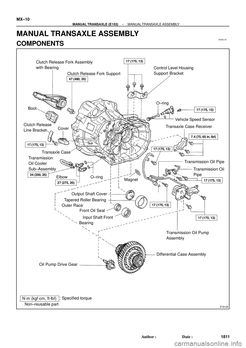
MX052±02
Z19124
Clutch Release Fork Assembly
with Bearing
Clutch Release Fork SupportControl Level Housing
Support Bracket
Boot�O±ring
Vehicle Speed Sensor
Transaxle Case Receiver Clutch Release
Line BracketCover
Transaxle Case
Transmission Oil
Pipe Transmission
Oil Cooler
Sub±Assembly
Elbow�O±ring
Magnet
�
Transmission Oil Pump
Assembly
Differential Case Assembly
Oil Pump Drive Gear�Output Shaft Cover
�Tapered Roller Bearing
Outer Race
�Front Oil Seal
�Input Shaft Front
Bearing
N´m (kgf´cm, ft´lbf): Specified torque
�Non±reusable part
47 (480, 35)
17 (175, 13)
17 (175, 13)
17 (175, 13)
17 (175, 13)
17 (175, 13)
7.4 (75, 65 in.´lbf)
17 (175, 13)
27 (275, 20)
34 (350, 25)
17 (175, 13)
Transmission Oil Pipe MX±10
± MANUAL TRANSAXLE (E153)MANUAL TRANSAXLE ASSEMBLY
1811 Author�: Date�:
MANUAL TRANSAXLE ASSEMBLY
COMPONENTS
Page 2951 of 4592
MANUAL TRANSAXLE ASSEMBLY
1819 Author�: Date�:
32. REMOVE INPUT AND OUTPUT SHAFTS ASSEMBLY
(a) Leaning the output shaft to the differential side, remove
the inp")
MT0781
MX±18
± MANUAL TRANSAXLE (E153)MANUAL TRANSAXLE ASSEMBLY
1819 Author�: Date�:
32. REMOVE INPUT AND OUTPUT SHAFTS ASSEMBLY
(a) Leaning the output shaft to the differential side, remove
the input shaft assembly.
(b) Lift up the differential case assembly, remove the output
shaft assembly.
33. REMOVE DIFFERENTIAL CASE ASSEMBLY
(a) Remove the oil pump drive gear.
(b) Remove the differential case assembly.
34. REMOVE MAGNET FROM TRANSAXLE CASE
35. REMOVE TRANSMISSION OIL PUMP ASSEMBLY
AND OIL PIPE
(a) Remove the 2 bolts and oil pipe.
Torque: 17 N´m (175 kgf´cm, 13 ft´lbf)
(b) Remove the 2 bolts and oil pump assembly.
Torque: 17 N´m (175 kgf´cm, 13 ft´lbf)
36. REMOVE NO.5 SYNCHRONIZER RING WITH KEY
SPRING FROM NO.3 CLUTCH HUB
(a) Remove the No.5 synchronizer ring with the key spring
from the No.3 clutch hub.
(b) Using a screwdriver, remove the snap ring.
HINT:
Wrap vinyl tape on the screwdriver to prevent damaging the
synchronizer ring.
(c) Remove the synchronizer rings.
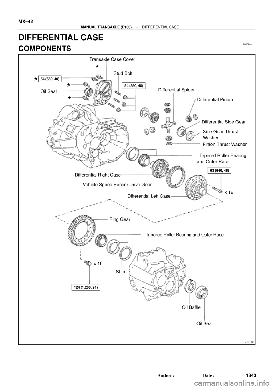
Page 2975 of 4592
MX05H±01
Z17560
Transaxle Case Cover
Stud Bolt �
54 (550, 40)
�54 (550, 40)
�
�Oil Seal
�Differential Spider
Differential Pinion
Differential Side Gear
Side Gear Thrust
Washer
Pinion Thrust Washer
�Tapered Roller Bearing
and Outer Race
63 (640, 46)
x 16 Differential Right Case
Vehicle Speed Sensor Drive Gear
Differential Left Case
Ring Gear
x 16�Tapered Roller Bearing and Outer Race
Shim
124 (1,260, 91)
Oil Baffle
�Oil Seal MX±42
± MANUAL TRANSAXLE (E153)DIFFERENTIAL CASE
1843 Author�: Date�:
DIFFERENTIAL CASE
COMPONENTS
Page 2976 of 4592
DIFFERENTIAL CASE
MX±43
1844 Author�: Date�:
DISASSEMBLY
1. REMOVE TAPERED ROLLER BEARING
Using SST, remove the left and")
MX05I±03
Q05166
SST
Z00281
Matchmarks
Z00284
Z00286
± MANUAL TRANSAXLE (E153)DIFFERENTIAL CASE
MX±43
1844 Author�: Date�:
DISASSEMBLY
1. REMOVE TAPERED ROLLER BEARING
Using SST, remove the left and right bearings.
SST 09950±40011
2. REMOVE RING GEAR
(a) Place matchmarks on both the differential case and ring
gear.
(b) Remove the 16 bolts.
(c) Using a plastic hammer, tap the ring gear and remove it.
3. DISASSEMBLE DIFFERENTIAL CASE
(a) Place matchmarks on the differential right and left cases.
(b) Using a torx wrench (T50), remove the 16 torx screws.
(c) Using a plastic hammer, tap the differential left case.
(d) Remove the vehicle speed sensor drive gear from the dif-
ferential right case.
(e) Remove the 2 differential side gears, side gear thrust
washers, 4 differential pinions and pinion thrust washers
from the differential left case.
4. Transmission Case Side:
IF NECESSARY, REPLACE OIL SEAL AND TAPERED
ROLLER BEARING OUTER RACE
(a) Using a screwdriver, remove the oil seal.
(b) Remove the oil baffle.
(c) Using a brass bar and hammer, drive out the bearing out-
er race lightly and evenly.
(d) Remove the shim.
(e) Install the shim. (See page MX±42)
HINT:
First select and install a shim of less thickness than before.
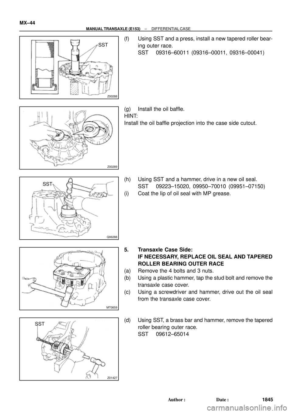
Page 2977 of 4592
Z00288
SST
Z00289
Q06288
SST
MT0659
Z01427
SST MX±44
± MANUAL TRANSAXLE (E153)DIFFERENTIAL CASE
1845 Author�: Date�:
(f) Using SST and a press, install a new tapered roller bear-
ing outer race.
SST 09316±60011 (09316±00011, 09316±00041)
(g) Install the oil baffle.
HINT:
Install the oil baffle projection into the case side cutout.
(h) Using SST and a hammer, drive in a new oil seal.
SST 09223±15020, 09950±70010 (09951±07150)
(i) Coat the lip of oil seal with MP grease.
5. Transaxle Case Side:
IF NECESSARY, REPLACE OIL SEAL AND TAPERED
ROLLER BEARING OUTER RACE
(a) Remove the 4 bolts and 3 nuts.
(b) Using a plastic hammer, tap the stud bolt and remove the
transaxle case cover.
(c) Using a screwdriver and hammer, drive out the oil seal
from the transaxle case cover.
(d) Using SST, a brass bar and hammer, remove the tapered
roller bearing outer race.
SST 09612±65014