Page 101 of 4592
VALVE BODY ASSEMBLY
AX±7
1900 Author�: Date�:
12. I")
OR0038
Z10942
C
DB
A
CBA B
AT0492
AT7870
Z10941 AT0493
Shift Solenoid Valve No.2
BlackWhite
Shift Solenoid Valve No.1
± AUTOMATIC TRANSAXLE (A140E)VALVE BODY ASSEMBLY
AX±7
1900 Author�: Date�:
12. INSTALL SHIFT SOLENOID VALVE NO.1 AND NO.2
(a) Coat 2 new O±rings with ATF.
(b) Install the 2 O±rings to the shift solenoid valve No.1 and
No.2.
(c) Install the shift valve No.1 with the 2 bolts.
Torque: 5.4 N´m (55 kgf´cm, 48 in.´lbf)
(d) Install the shift valve No.2 with the bolt.
Torque: 5.4 N´m (55 kgf´cm, 48 in.´lbf)
13. INSTALL NEW 2ND BRAKE APPLY GASKET
14. INSTALL VALVE BODY
(a) While holding the cam down by your hand, slip the cable
end into the slot.
NOTICE:
Do not entangle the solenoid wire.
(b) Install the valve body with the 12 bolts.
HINT:
Temporarily install the 12 bolts first, then tighten the 12 bolts.
Torque: 10 N´m (100 kgf´cm, 7 ft´lbf)
Bolt length:
Bolt A: 20 mm (0.79 in.)
Bolt B: 25 mm (0.98 in.)
Bolt C: 36 mm (1.42 in.)
Bolt D: 50 mm (1.97 in.)
15. INSTALL OIL PIPES
Using a plastic hammer, install the 4 pipes into the positions in-
dicated in the illustration.
NOTICE:
Be careful not to bend or damage the pipes.
16. CONNECT SOLENOID CONNECTORS
Connect the black wire harness to shift solenoid valve No.2 and
white wire harness to shift solenoid valve No.1.
Page 131 of 4592
VALVE BODY ASSEMBLY
1930 Author�: Date�:
(d) Coat the 2 new O±rings with ATF and install it to the shift
solenoid")
Q05402
Q05643
OR0038
D01023
A
C
CB
C
DD
D01058
AX±10
± AUTOMATIC TRANSAXLE (A541E)VALVE BODY ASSEMBLY
1930 Author�: Date�:
(d) Coat the 2 new O±rings with ATF and install it to the shift
solenoid valve SLN.
(e) Install the shift solenoid valve SLN.
(f) Install and torque the bolt.
Torque: 6.6 N´m (67 kgf´cm, 58 in.´lbf)
(g) Coat the 2 new O±rings with ATF and install it to the shift
solenoid valve No.1 and No.2.
(h) Install the No.1 and No.2 solenoids.
(i) Install and torque the 3 bolts.
Torque: 6.6 N´m (67 kgf´cm, 58 in.´lbf)
15. PLACE NEW 2ND BRAKE APPLY GASKET
16. INSTALL VALVE BODY TO TRANSAXLE CASE
(a) While holding the cam down with your hand, slip the cable
end into the slot.
(b) Lower the valve body into place.
NOTICE:
Be careful not to entangle the solenoid wire.
(c) Install and tighten the 9 bolts.
HINT:
Hand tighten the 9 bolts first, then torque with a torque wrench.
Bolt length:
Bolt A: 30 mm (1.181 in.)
Bolt B: 43 mm (1.693 in.)
Bolt C: 48 mm (1.890 in.)
Bolt D: 52 mm (2.047 in.)
Torque: 11 N´m (110 kgf´cm, 8 ft´lbf)
17. INSTALL B
3 APPLY PIPE
NOTICE:
Be careful not to bend or damage the pipe.
Page 132 of 4592

BAmm (in.)
Q05728
Connector
± AUTOMATIC TRANSAXLE (A541E)VALVE BODY ASSEMBLY
AX±11
1931 Author�: Date�:
18. INSTALL CONNECTOR CLAMP AND PIPE RETAINER
(a) Ins")
D01059
A
B
D01021
B
B
A
Z19257
30
(1.18)
BAmm (in.)
Q05728
Connector
± AUTOMATIC TRANSAXLE (A541E)VALVE BODY ASSEMBLY
AX±11
1931 Author�: Date�:
18. INSTALL CONNECTOR CLAMP AND PIPE RETAINER
(a) Install the connector clamp and pipe retainer.
(b) Install and torque the 2 bolts.
Bolt length:
Bolt A: 48 mm (1.890 in.)
Bolt B: 39 mm (1.535 in.)
Torque: 11 N´m (110 kgf´cm, 8 ft´lbf)
19. INSTALL MANUAL VALVE BODY
(a) Align the manual valve with the pin on the manual shaft
lever.
(b) Lower the manual valve body into place.
(c) Hand tighten the 5 bolts first. Then, tighten them with a
torque wrench.
Bolt length:
Bolt A: 22 mm (0.866 in.)
Bolt B: 37 mm (1.457 in.)
Torque: 11 N´m (110 kgf´cm, 8 ft´lbf)
20. INSTALL DETENT SPRING AND OIL PIPE
(a) Place the detent springs on the manual valve body and
hand tighten the 2 bolts first. Then, tighten them with a
torque wrench.
Bolt length:
Bolt A: 14 mm (0.551 in.)
Bolt B: 37 mm (1.457 in.)
Torque: 11 N´m (110 kgf´cm, 8 ft´lbf)
(b) Check that the manual valve lever is touching the center
of the detent spring tip roller.
(c) Using a plastic hammer, install the pipe into the position.
NOTICE:
Be careful not to bend or damage the pipe.
(d) Install and torque the bolt.
Torque: 10 N´m (100 kgf´cm, 7 ft´lbf)
21. CONNECT SOLENOID CONNECTORS
22. INSTALL OIL PIPES
Using a plastic hammer, install the pipes into the positions.
NOTICE:
Be careful not to bend or damage the pipes.
Page 133 of 4592
Z19256
BA
B A
AT3741
AT3785
AX±12
± AUTOMATIC TRANSAXLE (A541E)VALVE BODY ASSEMBLY
1932 Author�: Date�:
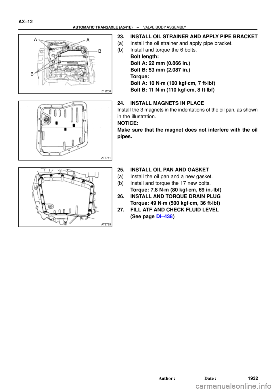
23. INSTALL OIL STRAINER AND APPLY PIPE BRACKET
(a) Install the oil strainer and apply pipe bracket.
(b) Install and torque the 6 bolts.
Bolt length:
Bolt A: 22 mm (0.866 in.)
Bolt B: 53 mm (2.087 in.)
Torque:
Bolt A: 10 N´m (100 kgf´cm, 7 ft´lbf)
Bolt B: 11 N´m (110 kgf´cm, 8 ft´lbf)
24. INSTALL MAGNETS IN PLACE
Install the 3 magnets in the indentations of the oil pan, as shown
in the illustration.
NOTICE:
Make sure that the magnet does not interfere with the oil
pipes.
25. INSTALL OIL PAN AND GASKET
(a) Install the oil pan and a new gasket.
(b) Install and torque the 17 new bolts.
Torque: 7.8 N´m (80 kgf´cm, 69 in.´lbf)
26. INSTALL AND TORQUE DRAIN PLUG
Torque: 49 N´m (500 kgf´cm, 36 ft´lbf)
27. FILL ATF AND CHECK FLUID LEVEL
(See page DI±438)
Page 166 of 4592
Total No. of coils and Color
Upper valve body
Throttle modulator valve21.7")
AUTOMATIC TRANSAXLESERVICE SPECIFICATIONS ±
AX±14
Valve Body Spring
SpringFree length and Coil outer
diameter mm (in.)Total No. of coils and Color
Upper valve body
Throttle modulator valve21.7 (0.854)
9.5 (0.374)9.5
None
Accumulator control valve28.1 (0.105)
10.6 (0.417)13.0
Yellow
Low coast modulator valve21.6 (0.850)
7.9 (0.311)11.5
None
Down shift plug29.8 (1.172)
8.7 (0.344)13.5
Yellow
Throttle valve30.7 (1.209)
9.2 (0.362)9.5
None
Second coast modulator valve20.9 (0.824)
8.5 (0.336)10.0
Light Green
Cut±back valve21.8 (0.858)
6.0 (0.236)13.5
None
Lock±up relay valve26.6 (1.046)
10.2 (0.402)11.5
Green
Lower valve body
Pressure relief valve11.2 (0.441)
6.4 (0.252)7.5
None
1 ± 2 shift valve29.3 (1.152)
9.7 (0.382)10.5
None
2 ± 3 shift valve29.3 (1.152)
9.7 (0.382)10.5
None
3 ± 4 shift valve29.3 (1.152)
9.7 (0.382)10.5
None
Primary regulator valve66.7 (2.453)
18.6 (0.732)12.5
None
Secondary regulator valve43.6 (1.717)
10.9 (0.429)11.5
None
Lock±up signal valve30.0 (1.181)
8.2 (0.323)11.5
None
Cooler By±pass valve19.9 (0.784)
11.0 (0.433)8.5
None
Valve Body Retainer
ReteinerHeight
mm (in.)Width
mm (in.)Thickness
mm (in.)
Upper valve body
Throttle Modulator valve9.2 (0.362)5.0 (0.197)3.2 (0.126)
Accumulator control valve11.5 (0.453)5.0 (0.197)3.2 (0.126)
Cut±back valve9.2 (0.591)5.0 (0.197)3.2 (0.126)
Lock±up relay valve15.0 (0.591)5.0 (0.197)3.2 (0.126)
Second coast modulator valve15.0 (0.591)5.0 (0.197)3.2 (0.126)
Lower valve body
Primary regulator valve9.2 (0.362)5.0 (0.197)3.2 (0.126)
Page 167 of 4592
AUTOMATIC TRANSAXLESERVICE SPECIFICATIONS ±
AX±15
1 ± 2 shift valve9.2 (0.362)5.0 (0.197)3.2 (0.126)
2 ± 3 shift valve8.0 (0.315)5.0 (0.197)3.2 (0.126)
3 ± 4 shift valve8.0 (0.315)5.0 (0.197)3.2 (0.126)
Lock±up signal valve15.0 (0.591)5.0 (0.197)3.2 (0.126)
Accumulator Spring
SpringFree length mm (in.)Color
C157.64 (2.2693)Red, Purple
B269.39 (2.7323)Green, White
C270.21 (2.7641)Purple
Page 204 of 4592
AUTOMATIC TRANSAXLESECOND COAST BRAKE ±
AX±34
(b) Remove the spring, washer and piston rod.
SECOND COAST BRAKE INSPECTION
INSPECT BRAKE BAND
If the lining of the brake band is peeling off or discolored,
or even if a part of the printed numbers are defaced, re-
place the brake band.
SECOND COAST BRAKE PISTON
ASSEMBLY
1. SELECT PISTON ROD
If the band is OK, but the piston stroke is not within the
standard value, select a new piston rod.
Piston stroke:
1.5 ± 3.0 mm (0.059 ± 0.118 in.)
There are 2 lengths of piston rod.
Piston rod length:
72.9 mm (2.870 in.)
71.4 mm (2.811 in.)
2. INSTALL PISTON ROD
(a) Install the washer and spring to the piston rod.
(b) Install an E±ring while pushing the piston.
AX0F1±02
AX0F2±02
Page 249 of 4592
AUTOMATIC TRANSAXLEVALVE BODY ±
AX±79
2. PLACE LOWER VALVE BODY WITH PLATE AND GAS-
KETS ON UPPER VALVE BODY
HINT: Hold the lower valve body, gaskets and plate se-
curely so they do not separate.
Align each bolt hole in the valve bodies with the gaskets
and plate.
3. INSTALL AND FINGER TIGHTEN BOLTS IN LOWER
VALVE BODY TO SECURE UPPER VALVE BODY
Install and finger tighten the 3 bolts.
HINT: Each bolt length (mm, in.) is indicated in the illustra-
tion.
4. INSTALL LOWER VALVE BODY COVER
(a) Install the lower valve body cover over the new gasket.
(b) Install and finger tighten the 10 bolts.
HINT: Each bolt length (mm, in.) is indicated in the illustra-
tion.
5. INSTALL AND FINGER TIGHTEN BOLTS IN UPPER
VALVE BODY
Install and finger tighten the 3 bolts.
HINT: Each bolt length (mm, in.) is indicated in the illustra-
tion.
6. INSTALL SLEEVE STOPPER
5.0 (0.197)3.2 (0.126)
2 ± 3 shift valve8.0 (0.315)5.0 (0.197)3.2 (0.126)
3 ± 4 shift valve8.0 (0.315)5.0 (0.19")
 Remove the spring, washer and piston rod.
SECOND COAST BRAKE INSPECTION
INSPECT BRAKE BAND
If the lining of the brake band is peeling off or discolo")
