Page 1442 of 4592
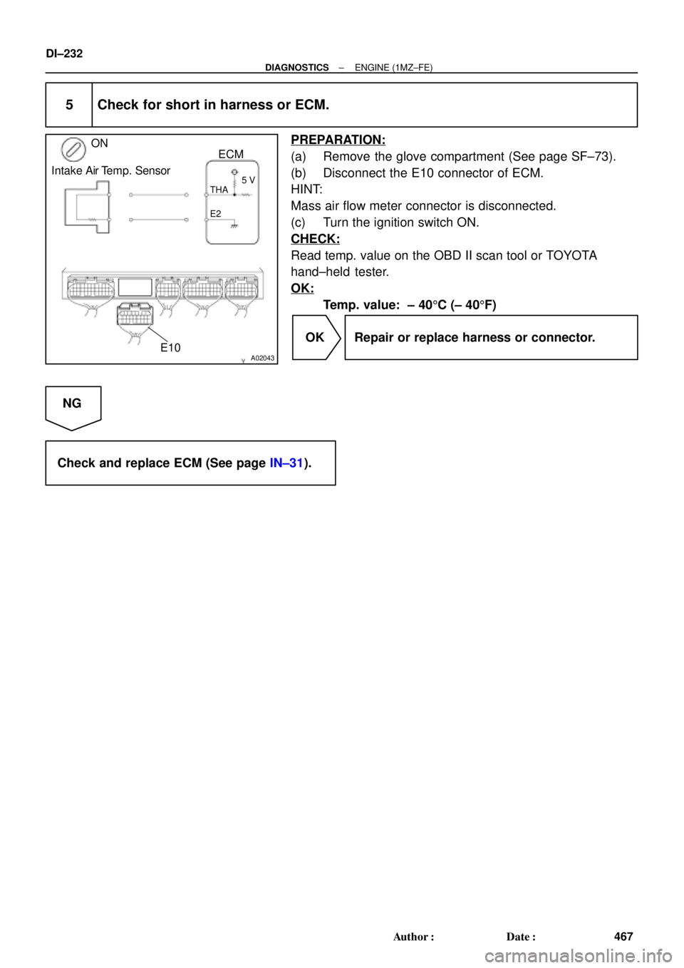
A00210
ON
Intake Air
Temp. Sensor
ECM
5 V
E2THA
1
2
E10 E10
22
18
DI±230
± DIAGNOSTICSENGINE (1MZ±FE)
465 Author�: Date�:
1 Connect OBD II scan tool or TOYOTA hand±held tester, and read value of
intake air temp.
PREPARATION:
(a) Connect the OBD II scan tool or TOYOTA hand±held tester to the DLC3.
(b) Turn the ignition switch ON and push the OBD II scan tool or TOYOTA hand±held tester main switch
ON.
CHECK:
Read temp. value on the OBD II scan tool or TOYOTA hand±held tester.
OK:
Same as actual intake air temp.
HINT:
�If there is open circuit, OBD II scan tool or TOYOTA hand±held tester indicates ±40°C (-40°F).
�If there is short circuit, OBD II scan tool or TOYOTA hand±held tester indicates 140°C (284°F) or more.
NG ±40°C (±40°F) ... Go to step 2.
140°C (284°F) or more ... Go to step 4.
OK
Check for intermittent problems
(See page DI±197).
2 Check for open in harness or ECM.
PREPARATION:
(a) Disconnect the mass air flow meter connector.
(b) Connect sensor wire harness terminals together.
(c) Turn the ignition switch ON.
CHECK:
Read temp. value on the OBD II scan tool or TOYOTA
hand±held tester.
OK:
Temp. value: 1405C (2845F) or more
OK Confirm good connection at sensor.
If OK, replace mass air flow meter.
NG
Page 1443 of 4592
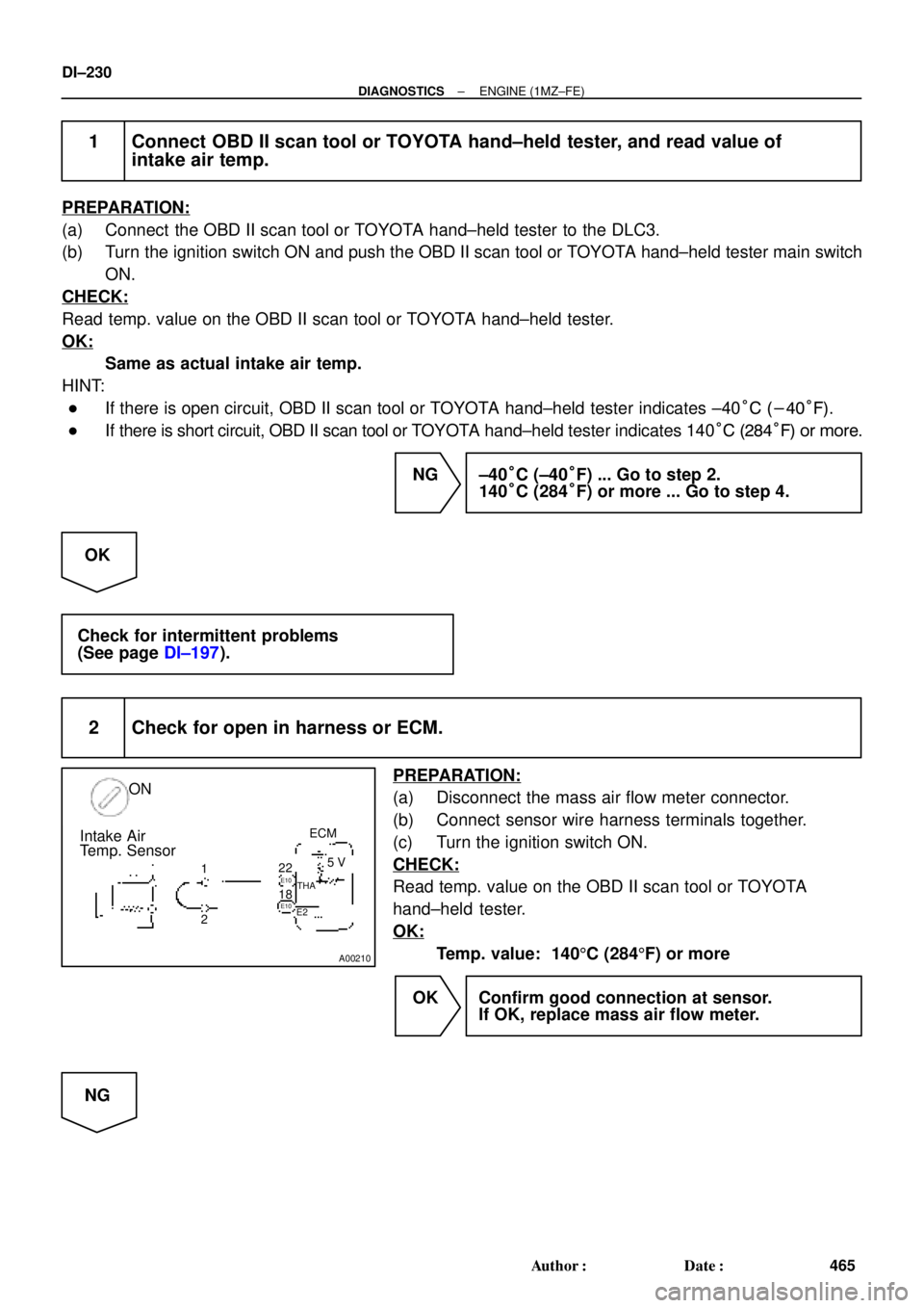
A02019
Intake Air Temp. Sensor ON22
18E10
E10THA5 V
E2
E2 THA
ECM
A00212
ON
Intake Air
Temp. Sensor
ECM
5 V
E2
22
THA
E10 E1018
± DIAGNOSTICSENGINE (1MZ±FE)
DI±231
466 Author�: Date�:
3 Check for open in harness or ECM.
PREPARATION:
(a) Remove the glove compartment (See page SF±73).
(b) Connect between terminals THA and E2 of ECM connec-
tor.
HINT:
Mass air flow meter connector is disconnected.
Before checking, do a visual and contact pressure check for the
ECM connector (See page IN±31).
CHECK:
Read temp. value on the OBD II scan tool or TOYOTA
hand±held tester.
OK:
Temp. value: 1405C (2845F) or more
OK Open in harness between terminal E2 or THA,
repair or replace harness.
NG
Confirm good connection at ECM.
If OK, check and replace ECM.
4 Check for short in harness and ECM.
PREPARATION:
(a) Disconnect the mass air flow meter connector.
(b) Turn the ignition switch ON.
CHECK:
Read temp. value on the OBD II scan tool or TOYOTA
hand±held tester.
OK:
Temp. value: ±405C (±405F)
OK Replace mass air flow meter.
NG
Page 1444 of 4592
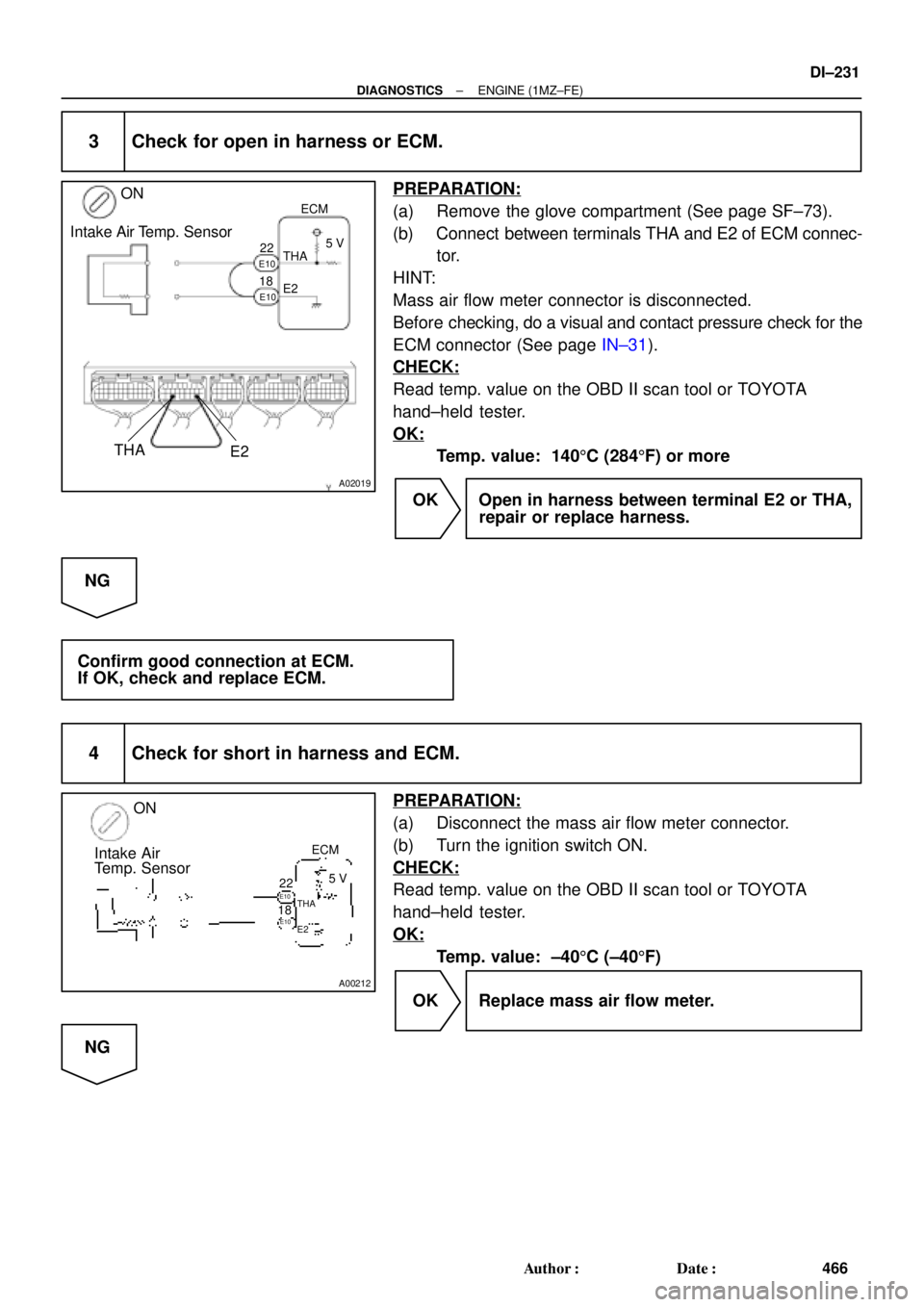
A02043
ON
Intake Air Temp. Sensor
E10
THA
E25 V
ECM
DI±232
± DIAGNOSTICSENGINE (1MZ±FE)
467 Author�: Date�:
5 Check for short in harness or ECM.
PREPARATION:
(a) Remove the glove compartment (See page SF±73).
(b) Disconnect the E10 connector of ECM.
HINT:
Mass air flow meter connector is disconnected.
(c) Turn the ignition switch ON.
CHECK:
Read temp. value on the OBD II scan tool or TOYOTA
hand±held tester.
OK:
Temp. value: ± 405C (± 405F)
OK Repair or replace harness or connector.
NG
Check and replace ECM (See page IN±31).
Page 1480 of 4592

DI±268
± DIAGNOSTICSENGINE (1MZ±FE)
503 Author�: Date�:
HINT:
�When the DTC P0171 is recorded, the actual air±fuel ratio is on the lean side. When DTC P0172 is
recorded, the actual air±fuel ratio is on the rich side.
�If the vehicle runs out of fuel, the air±fuel ratio is lean and DTC P0171 is recorded. The MIL then comes
on.
�If the total of the short±term fuel trim value and long±term fuel trim value is within + 35 % (80°C (176°F)
or more), the system is functioning normally.
�The A/F sensors (bank 1, 2 sensor 1) output voltage and the short±term fuel trim value can be read
using the OBD II scan tool or TOYOTA hand±held tester.
�The ECM controls the voltage of AFR�, AFL�, AFR� and AFL� terminals of ECM to the fixed volt-
age. Therefore, it is impossible to confirm the A/F sensor output voltage without OBD II scan tool or
TOYOTA hand±held tester.
�OBD II scan tool (excluding TOYOTA hand±held tester) displays the one fifth of the A/F sensors (bank
1, 2 sensor 1) output voltage which is displayed on the TOYOTA hand±held tester.
INSPECTION PROCEDURE
Read freeze frame data using TOYOTA hand±held tester or OBD II scan tool. Because freeze frame records
the engine conditions when the malfunction is detected, when troubleshooting it is useful for determining
whether the vehicle was running or stopped, the engine warmed up or not, the air±fuel ratio lean or rich, etc.
at the time of the malfunction.
1 Check air induction system (See page SF±1).
NG Repair or replace.
OK
2 Check injector injection (See page SF±25).
NG Replace injector.
OK
3 Check mass air flow meter and engine coolant temp. sensor
(See pages SF±35 and SF±63).
NG Repair or replace.
OK
Page 1485 of 4592
± DIAGNOSTICSENGINE (1MZ±FE)
DI±273
508 Author�: Date�:
1 Check air induction system (See page SF±1).
NG Repair or replace.
OK
2 Check injector injection (See page SF±21).
NG Replace injector.
OK
3 Check mass air flow meter and engine coolant temp. sensor
(See pages SF±35 and SF±63).
NG Repair or replace.
OK
4 Check for spark and ignition (See page IG±1).
NG Repair or replace.
OK
5 Check fuel pressure (See page SF±6).
NG Check and repair fuel pump, pressure regulator,
fuel pipe line and filter.
OK
Page 1494 of 4592
DI±282
± DIAGNOSTICSENGINE (1MZ±FE)
517 Author�: Date�:
8 Check mass air flow meter and engine coolant temp. sensor
(See pages SF±35, SF±63).
NG Repair or replace.
OK
Check compression pressure, valve
clearance and valve timing.