Page 3618 of 4592
SA08F±01
SA±62
± SUSPENSION AND AXLEREAR SHOCK ABSORBER
2013 Author�: Date�:
INSTALLATION
Installation is in the reverse order of removal (See page SA±57).
AFTER INSTALLATION, CHECK REAR WHEEL ALIGNMENT (See page SA±7)
Page 3623 of 4592
SA08J±01
W03222
W03223
AB
W03224
± SUSPENSION AND AXLEREAR LOWER SUSPENSION ARM AND STRUT ROD
SA±67
2018 Author�: Date�:
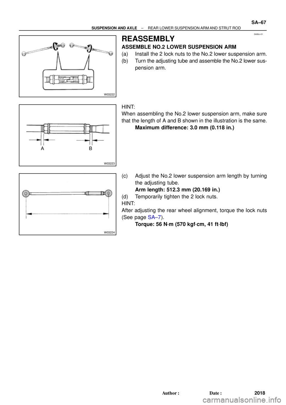
REASSEMBLY
ASSEMBLE NO.2 LOWER SUSPENSION ARM
(a) Install the 2 lock nuts to the No.2 lower suspension arm.
(b) Turn the adjusting tube and assemble the No.2 lower sus-
pension arm.
HINT:
When assembling the No.2 lower suspension arm, make sure
that the length of A and B shown in the illustration is the same.
Maximum difference: 3.0 mm (0.118 in.)
(c) Adjust the No.2 lower suspension arm length by turning
the adjusting tube.
Arm length: 512.3 mm (20.169 in.)
(d) Temporarily tighten the 2 lock nuts.
HINT:
After adjusting the rear wheel alignment, torque the lock nuts
(See page SA±7).
Torque: 56 N´m (570 kgf´cm, 41 ft´lbf)
Page 3624 of 4592
SA08K±01
SA±68
± SUSPENSION AND AXLEREAR LOWER SUSPENSION ARM AND STRUT ROD
2019 Author�: Date�:
INSTALLATION
Installation is in the reverse order of removal (See page SA±64).
AFTER INSTALLATION, CHECK REAR WHEEL ALIGNMENT (See page SA±7)
Page 3629 of 4592

F08080
Front:
Rear:SA1DP±03
Z03382
± SUSPENSION AND AXLEFRONT WHEEL ALIGNMENT
SA±1
508 Author�: Date�:
FRONT WHEEL ALIGNMENT
INSPECTION
1. MEASURE VEHICLE HEIGHT
Vehicle height:
Tire sizeFront*1 mm (in.)Rear*2 mm (in.)
205/65R15218 (8.58)270 (10.63)
*1: Front measuring point
Measure the distance from the ground to the center of the front
side lower suspension arm mounting bolt.
*
2: Rear measuring point
Measure the distance from the ground to the center of the front
side strut rod mounting bolt.
NOTICE:
Before inspecting the wheel alignment, adjust the vehicle
height to the specified value.
If the vehicle height is not the specified value, try to adjust it by
pushing down on or lifting the body.
2. INSTALL CAMBER±CASTER±KINGPIN GAUGE OR
POSITION VEHICLE ON WHEEL ALIGNMENT TES-
TER
Follow the specific instructions of the equipment manufacturer.
3. INSPECT CAMBER, CASTER AND STEERING AXIS
INCLINATION
Camber, caster and steering axis inclination:
Camber
Right±left error±0°36' ± 45' (±0.6° ± 0.75°)
45' (0.75°) or less
Caster
Right±left error2°10' ± 45' (2.17° ± 0.75°)
45' (0.75°) or less
Steering axis inclination
Right±left error13°01' ± 45' (13.02° ± 0.75°)
45' (0.75°) or less
If the caster and steering axis inclination are not within the spe-
cified values, after the camber has been correctly adjusted, re-
check the suspension parts for damaged and/or worn out parts.
4. ADJUST CAMBER
NOTICE:
After the camber has been adjusted, inspect the toe±in.
(a) Remove the front wheel and ABS speed sensor clamp.
Page 3630 of 4592

F04031
F04048
1
2
F01195
Bolt
Adjusting
ValueSet Bolt
15'
30'Adjusting Bolt90105±15001 90105±15004 90105±15005 90105±15006
45'
1°00'
1°15'
1°30'121212121 Dot
2 Dots3 Dots SA±2
± SUSPENSION AND AXLEFRONT WHEEL ALIGNMENT
509 Author�: Date�:
(b) Remove the 2 nuts on the lower side of the shock absorb-
er.
(c) Coat the threads of the nuts with engine oil.
(d) Temporarily install the 2 nuts.
(e) Adjust the camber by pushing or pulling the lower side of
the shock absorber in the direction in which the camber
adjustment is required.
(f) Tighten the nuts.
Torque: 211 N´m (2,150 kgf´cm, 156 ft´lbf)
(g) Install the ABS speed sensor clamp and front wheel.
Torque: 103 N´m (1,050 kgf´cm, 76 ft´lbf)
(h) Check the camber.
HINT:
�Try to adjust the camber to the center of the specified val-
ue.
�Adjusting value for the set bolts is 6' ± 30' (0.1° ± 0.5°).
If the camber is not within the specified value, using the follow-
ing table, estimate how much additional camber adjustment will
be required, and select the camber adjusting bolt.
(i) Do the steps mentioned above again. Between step (b)
and (c), replace 1 or 2 selected bolts.
HINT:
When replacing the 2 bolts, replace 1 bolt for each time.
Page 3631 of 4592
A + B: 0° �")
SA3213
Front A
DB
C
F02245
F02246
SA0028
Front AB
A B
A: Inside
B: Outside
± SUSPENSION AND AXLEFRONT WHEEL ALIGNMENT
SA±3
510 Author�: Date�:
5. INSPECT TOE±IN
Toe±in:
Toe±in
(total)A + B: 0° ± 12' (0° ± 0.2°)
C ± D: 0 ± 2 mm (0 ± 0.08 in.)
If the toe±in is not within the specified value, adjust it at the rack
ends.
6. ADJUST TOE±IN
(a) Using pliers, remove the rack boot set clips.
(b) Loosen the tie rod end lock nuts.
(c) Turn the right and left rack ends by an equal amount to
adjust the toe±in.
HINT:
Try to adjust the toe±in to the center of the specified value.
(d) Make sure that the lengths of the right and left rack ends
are the same.
Rack end length difference: 1.5 mm (0.059 in.) or less
(e) Torque the tie rod end lock nuts.
Torque: 74 N´m (750 kgf´cm, 54 ft´lbf)
(f) Place the boots on the seats and using pliers, install the
clips.
HINT:
Make sure that the boots are not twisted.
7. INSPECT WHEEL ANGLE
Turn the steering wheel fully, and measure the turning angle.
Wheel turning angle:
Inside wheel35°50' ± 2° (35.84° ± 2°)
Outside wheel: Reference31°28' (31.47°)
If the right and left inside wheel angles differ from the specified
value, check the right and left rack end lengths.
Page 3642 of 4592
 Install a new snap ring to the inboard joint shaft.
(b) Coat the gear oil")
SA1EC±02
SA±14
± SUSPENSION AND AXLEFRONT DRIVE SHAFT
INSTALLATION
1. LH drive shaft:
INSTALL DRIVE SHAFT TO TRANSAXLE
(a) Install a new snap ring to the inboard joint shaft.
(b) Coat the gear oil to the inboard joint shaft and differential case sliding surface.
(c) Set the snap ring with opening side facing downward.
(d) Using a brass bar and hammer, install the drive shaft.
NOTICE:
Be careful not to damage the dust cover of the drive shaft and oil seal lip of the transaxle.
HINT:
Whether the inboard joint shaft is in contact with the pinion shaft or not can be known from the sound or feel-
ing when driving it in.
(e) Check that there is 2 ± 3 mm (0.08 ± 0.12 in.) of play in the axial direction.
(f) Check that the drive shaft cannot be removed by hand.
2. RH drive shaft:
INSTALL DRIVE SHAFT TO TRANSAXLE
(a) Install the drive shaft.
NOTICE:
Be careful not to damage the dust cover of the drive shaft and oil seal lip of the transaxle.
(b) Using pliers, install a new snap ring.
(c) Install a new bearing lock bolt.
Torque: 32 N´m (330 kgf´cm, 24 ft´lbf)
3. CONNECT DRIVE SHAFT TO AXLE HUB
NOTICE:
Be careful not to damage the boot and ABS speed sensor rotor.
4. CONNECT LOWER SUSPENSION ARM TO LOWER BALL JOINT
Torque: 127 N´m (1,300 kgf´cm, 94 ft´lbf)
5. CONNECT TIE ROD END TO STEERING KNUCKLE
(a) Connect the tie rod end to the steering knuckle.
(b) Install the nut and a new cotter pin.
If the holes for the cotter pin are not aligned, tighten the nut further up to 60°.
Torque: 49 N´m (500 kgf´cm, 36 ft´lbf)
6. INSTALL DRIVE SHAFT LOCK NUT
(a) While applying brakes, install the nut.
Torque: 294 N´m (3,000 kgf´cm, 217 ft´lbf)
(b) Install the lock cap and a new cotter pin.
If the holes for the cotter pin are not aligned, tighten the nut further up to 60°.
7. FILL AND CHECK ATF (See page DI±133)
8. INSTALL FRONT FENDER APRON SEAL
9. INSTALL FRONT WHEEL
Torque: 103 N´m (1,050 kgf´cm, 76 ft´lbf)
10. CHECK FRONT WHEEL ALIGNMENT (See page SA±1)
11. CHECK ABS SPEED SENSOR SIGNAL (See page DI±177)
Page 3647 of 4592
 Install the 3 nuts and shock absorber with the coil spring.
Torque: 39 N´m (400")
SA1F5±02
± SUSPENSION AND AXLEREAR SHOCK ABSORBER
SA±19
INSTALLATION
1. INSTALL SHOCK ABSORBER WITH COIL SPRING
(a) Install the 3 nuts and shock absorber with the coil spring.
Torque: 39 N´m (400 kgf´cm, 29 ft´lbf)
(b) Install the shock absorber with the coil spring, 2 bolts and nuts.
Torque:
Reused nut: 196 N´m (2,000 kgf´cm, 145 ft´lbf)
New nut: 255 N´m (2,600 kgf´cm, 188 ft´lbf)
HINT:
If reusing the 2 nuts, coat the threads of the 2 nuts with engine oil.
(c) Torque the nut in the center of the suspension support.
Torque: 49 N´m (500 kgf´cm, 36 ft´lbf)
HINT:
If the shock absorber has not been disassembled, it is not necessary to torque the nut.
(d) Install the cap.
2. CONNECT STABILIZER BAR LINK
Torque: 39 N´m (400 kgf´cm, 29 ft´lbf)
HINT:
If the ball joint turns together with the nut, use a hexagon (5 mm) wrench to hold the stud.
3. CONNECT FLEXIBLE HOSE AND ABS SPEED SENSOR WIRE HARNESS CLAMP
Torque:
Flexible hose: 29 N´m (300 kgf´cm, 22 ft´lbf)
ABS speed sensor wire harness: 5.4 N´m (55 kgf´cm, 48 in.´lbf)
4. INSTALL REAR WHEEL
Torque: 103 N´m (1,050 kgf´cm, 76 ft´lbf)
5. INSTALL REAR SEATBACK AND REAR SEAT CUSHION (See page BO±25)
6. CHECK REAR WHEEL ALIGNMENT (See Pub. No. RM654U on page SA±7)