Page 3564 of 4592
W03091
SA±8
± SUSPENSION AND AXLEREAR WHEEL ALIGNMENT
1959 Author�: Date�:
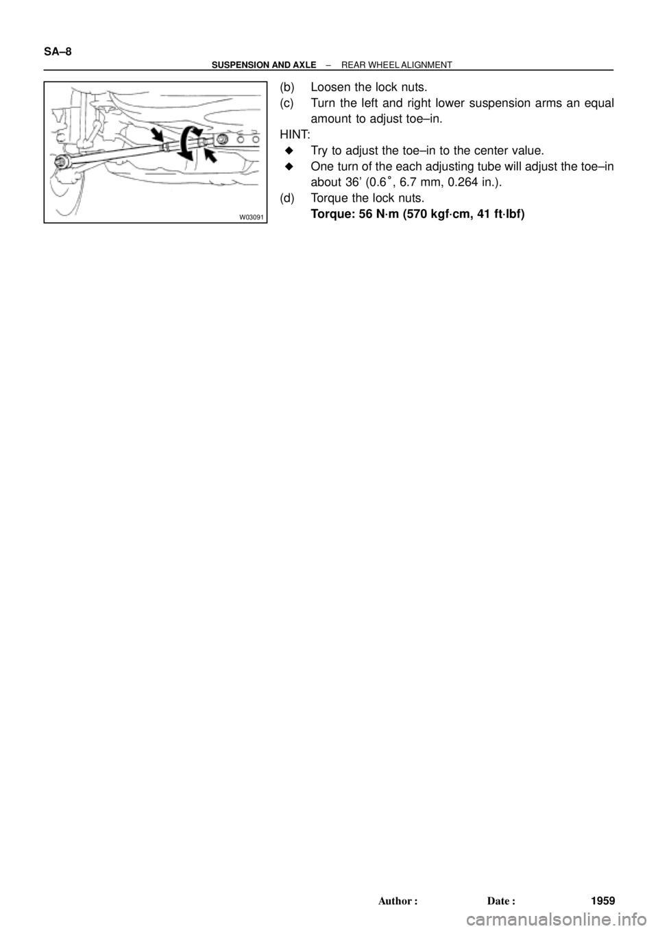
(b) Loosen the lock nuts.
(c) Turn the left and right lower suspension arms an equal
amount to adjust toe±in.
HINT:
�Try to adjust the toe±in to the center value.
�One turn of the each adjusting tube will adjust the toe±in
about 36' (0.6°, 6.7 mm, 0.264 in.).
(d) Torque the lock nuts.
Torque: 56 N´m (570 kgf´cm, 41 ft´lbf)
Page 3570 of 4592
SA07F±01
SA±14
± SUSPENSION AND AXLEFRONT AXLE HUB
1965 Author�: Date�:
INSTALLATION
Installation is in the reverse order of removal (See page SA±10).
AFTER INSTALLATION, CHECK ABS SPEED SENSOR SIGNAL (See page DI±493 or DI±539) AND
FRONT WHEEL ALIGNMENT (See page SA±4)
Page 3580 of 4592
SA08T±01
SA±24
± SUSPENSION AND AXLEFRONT DRIVE SHAFT (5S±FE)
1975 Author�: Date�:
INSTALLATION
Installation is in the reverse order of removal (See page SA±17).
AFTER INSTALLATION, CHECK ABS SPEED SENSOR SIGNAL (See page DI±493 or DI±539) AND
FRONT WHEEL ALIGNMENT(See page SA±4)
Page 3588 of 4592
SA07L±01
SA±32
± SUSPENSION AND AXLEFRONT DRIVE SHAFT (1MZ±FE)
1983 Author�: Date�:
INSTALLATION
Installation is in the reverse order of removal (See page SA±26).
AFTER INSTALLATION, CHECK ABS SPEED SENSOR SIGNAL (See page DI±493 or DI±539) AND
FRONT WHEEL ALIGNMENT (See page SA±4)
Page 3595 of 4592
SA07S±01
± SUSPENSION AND AXLEFRONT SHOCK ABSORBER
SA±39
1990 Author�: Date�:
INSTALLATION
Installation is in the reverse order of removal (See page SA±34).
AFTER INSTALLATION, CHECK FRONT WHEEL ALIGNMENT (See page SA±4)
Page 3598 of 4592
SA07W±01
SA±42
± SUSPENSION AND AXLEFRONT LOWER SUSPENSION ARM
1993 Author�: Date�:
INSTALLATION
Installation is in the reverse order of removal (See page SA±41).
AFTER INSTALLATION, CHECK FRONT WHEEL ALIGNMENT (See page SA±4)
Page 3602 of 4592
SA080±01
R08850
R08861
SST
SST SA±46
± SUSPENSION AND AXLEFRONT LOWER BALL JOINT
1997 Author�: Date�:
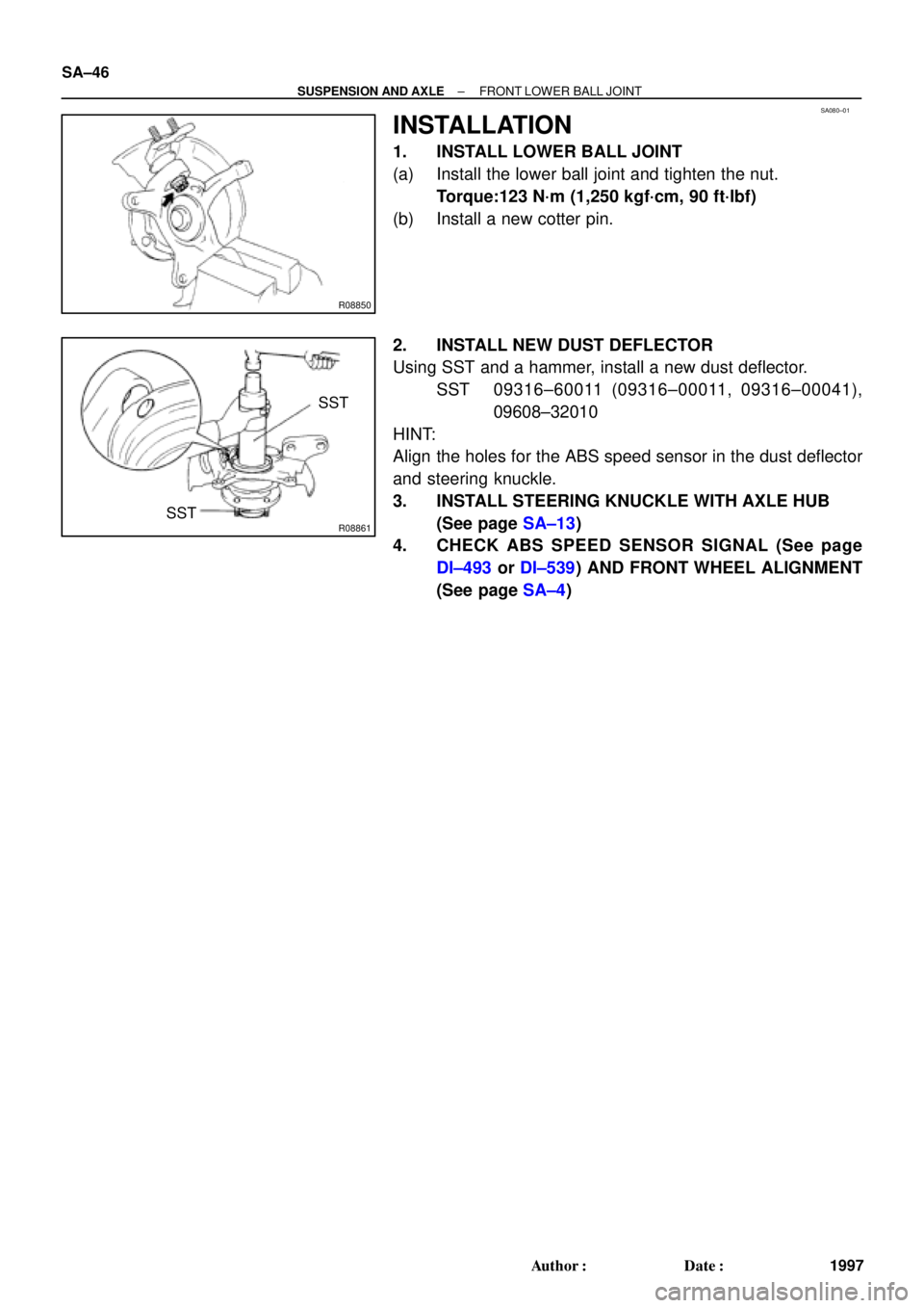
INSTALLATION
1. INSTALL LOWER BALL JOINT
(a) Install the lower ball joint and tighten the nut.
Torque:123 N´m (1,250 kgf´cm, 90 ft´lbf)
(b) Install a new cotter pin.
2. INSTALL NEW DUST DEFLECTOR
Using SST and a hammer, install a new dust deflector.
SST 09316±60011 (09316±00011, 09316±00041),
09608±32010
HINT:
Align the holes for the ABS speed sensor in the dust deflector
and steering knuckle.
3. INSTALL STEERING KNUCKLE WITH AXLE HUB
(See page SA±13)
4. CHECK ABS SPEED SENSOR SIGNAL (See page
DI±493 or DI±539) AND FRONT WHEEL ALIGNMENT
(See page SA±4)
Page 3610 of 4592
SA087±01
SA±54
± SUSPENSION AND AXLEREAR AXLE HUB
2005 Author�: Date�:
INSTALLATION
Installation is in the reverse order of removal (See page SA±52).
AFTER INSTALLATION, CHECK ABS SPEED SENSOR SIGNAL (See page DI±493 or DI±539) AND
REAR WHEEL ALIGNMENT (See page SA±7)