Page 2944 of 4592

Q10278
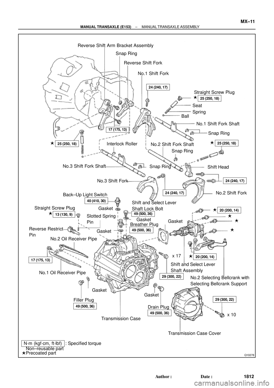
Reverse Shift Arm Bracket Assembly
Snap Ring
Reverse Shift Fork
No.1 Shift Fork
Straight Screw Plug
Seat
Spring
Ball
No.1 Shift Fork Shaft
Snap Ring
�
24 (240, 17)
25 (250, 18)
25 (250, 18)�
Interlock Roller
No.2 Shift Fork Shaft
Snap Ring
Shift Head25 (250, 18)�
No.3 Shift Fork Shaft
Snap Ring
No.3 Shift Fork
24 (240, 17)
24 (240, 17)
No.2 Shift Fork
Back±Up Light Switch
40 (410, 30)
Straight Screw Plug
13 (130, 9)Slotted Spring
Pin
Reverse Restrict
Pin
No.2 Oil Receiver PipeShift and Select Lever
Shaft Lock Bolt
Breather Plug
49 (500, 36)
20 (200, 14)
29 (300, 22)
�
�
�
�
20 (200, 14)x 17
Shift and Select Lever
Shaft Assembly
No.2 Selecting Bellcrank with
Selecting Bellcrank Support
29 (300, 22)
x 10
Transmission Case Cover �
Drain Plug49 (500, 36)
Transmission Case Filler Plug
49 (500, 36)
No.1 Oil Receiver Pipe
17 (175, 13)
N´m (kgf´cm, ft´lbf) : Specified torque
�Non±reusable part
�Precoated partGasket �Gasket
�Gasket
�Gasket
�Gasket�
�
49 (500, 36)
�Gasket
17 (175, 13)
± MANUAL TRANSAXLE (E153)MANUAL TRANSAXLE ASSEMBLY
MX±11
1812 Author�: Date�:
Page 2991 of 4592

MX04F±02
Z19123
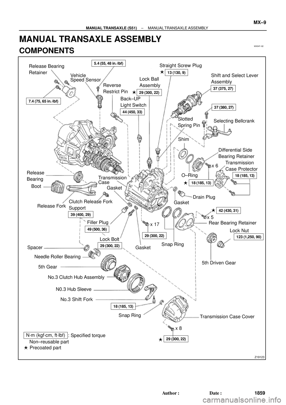
Transmission Case Cover5th Driven GearRear Bearing Retainer
No.3 Shift Fork N0.3 Hub Sleeve No.3 Clutch Hub Assembly Needle Roller BearingRelease ForkTransmission
CaseDifferential Side
Bearing Retainer
Transmission
Case Protector Straight Screw Plug
Shift and Select Lever
Assembly
Selecting Bellcrank Back±UP
Light SwitchLock Ball
Assembly Release Bearing
Retainer
Vehicle
Speed Sensor
Release
BearingReverse
Restrict Pin�
O±Ring �Shim
x 6 Slotted
Spring Pin
Gasket
Clutch Release Fork
Support
x 17
Snap RingLock Nut Filler Plug
Lock Boltx 5
Spacer
5th Gear
x 8 Boot
�
Gasket �
Gasket �Drain Plug
Snap Ring�
�
�
� �Non±reusable part
Precoated part: Specified torque
N´m (kgf´cm, ft´lbf)
5.4 (55, 48 in.´lbf)
13 (130, 9)
123 (1,250, 90)�
37 (375, 27)29 (300, 22)�
44 (450, 33)
18 (185, 13)
18 (185, 13)
42 (430, 31)
29 (300, 22)
29 (300, 22)
49 (500, 36)
39 (400, 29)
18 (185, 13)
29 (300, 22)
7.4 (75, 65 in.´lbf)
37 (380, 27)
± MANUAL TRANSAXLE (S51)MANUAL TRANSAXLE ASSEMBLY
MX±9
1859 Author�: Date�:
MANUAL TRANSAXLE ASSEMBLY
COMPONENTS
Page 3287 of 4592
± SERVICE SPECIFICATIONSMANUAL TRANSAXLE (E153)
SS±49
212 Author�: Date�:
Transmission oil pump assembly x Transaxle case1717513
Transaxle case receiver x Transaxle case7.47565 in.´lbf
Clutch release fork support4748035
Control lever housing support bracket x Transaxle case1717513
Vehicle speed sensor1717513
Clutch release line bracket x Transaxle case1717513
Back±up light switch4041030
Filler and drain plug4950036
No.1 and No.2 oil receiver pipe x Transmission case1717513
Transmission oil cooler sub±assembly x Elbow3435025
Elbow x Transaxle case2727520
Transmission oil pump case x Oil pump cover101058
Transaxle case cover x Transaxle case5455040
Differential left case x Differential right case6364046
Ring gear set bolt1241,26091
Page 3949 of 4592

TRANSMISSION OIL COOLER INSTALLATION ± TC003±97 October 17, 1997
Procedure3. Final Assembly:
(Continued)
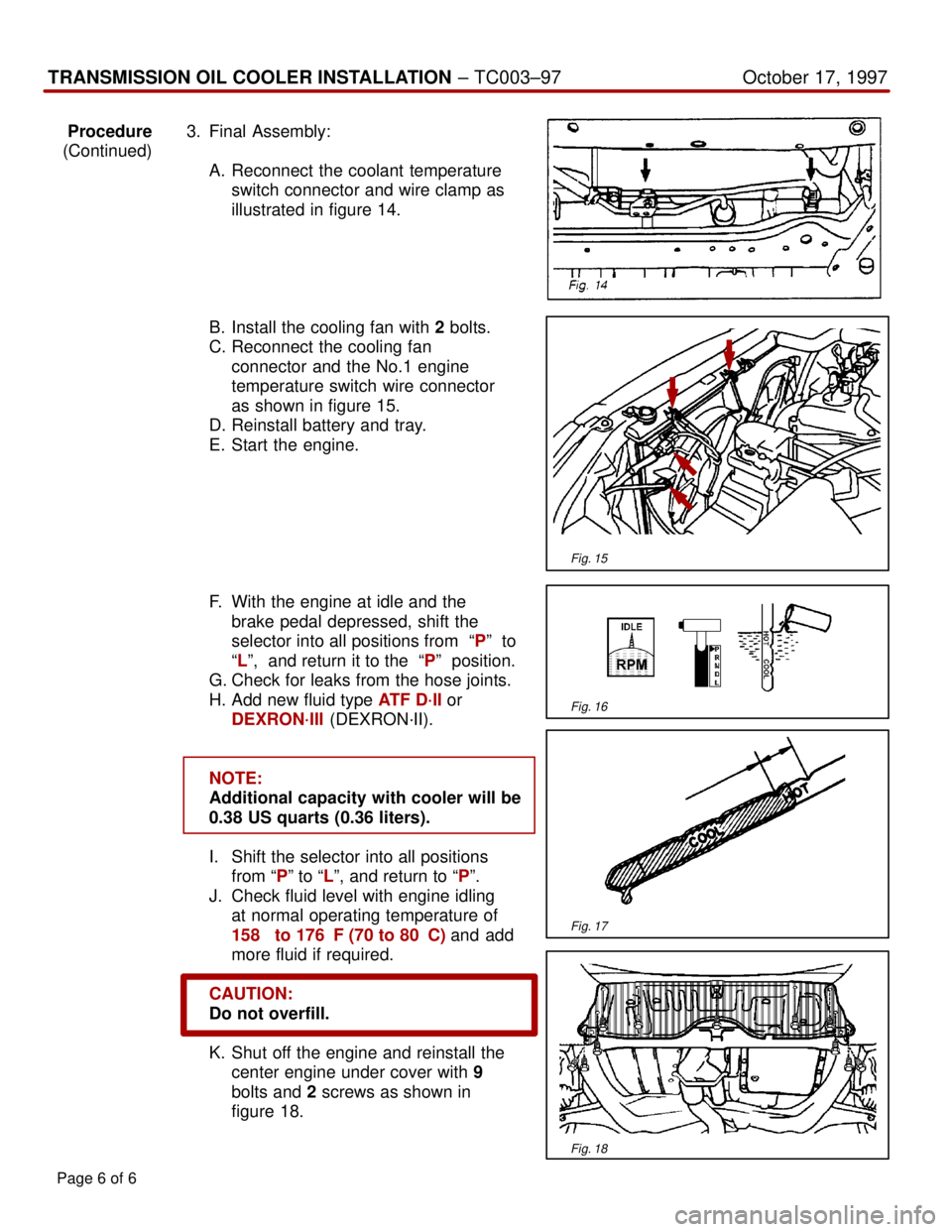
A. Reconnect the coolant temperature
switch connector and wire clamp as
illustrated in figure 14.
B. Install the cooling fan with 2 bolts.
C. Reconnect the cooling fan
connector and the No.1 engine
temperature switch wire connector
as shown in figure 15.
D. Reinstall battery and tray.
E. Start the engine.
F. With the engine at idle and the
brake pedal depressed, shift the
selector into all positions from ªPº to
ªLº, and return it to the ªPº position.
G. Check for leaks from the hose joints.
H. Add new fluid type ATF D´II or
DEXRON´III (DEXRON´II).
NOTE:
Additional capacity with cooler will be
0.38 US quarts (0.36 liters).
I. Shift the selector into all positions
from ªPº to ªLº, and return to ªPº.
J. Check fluid level with engine idling
at normal operating temperature of
158� to 176�F (70 to 80�C) and add
more fluid if required.
CAUTION:
Do not overfill.
K. Shut off the engine and reinstall the
center engine under cover with 9
bolts and 2 screws as shown in
figure 18.
Page 6 of 6
Fig. 15
Fig. 16
Fig. 17
Fig. 18