Page 55 of 4592
N20451
AC±54
± AIR CONDITIONINGCONDENSER
2536 Author�: Date�:
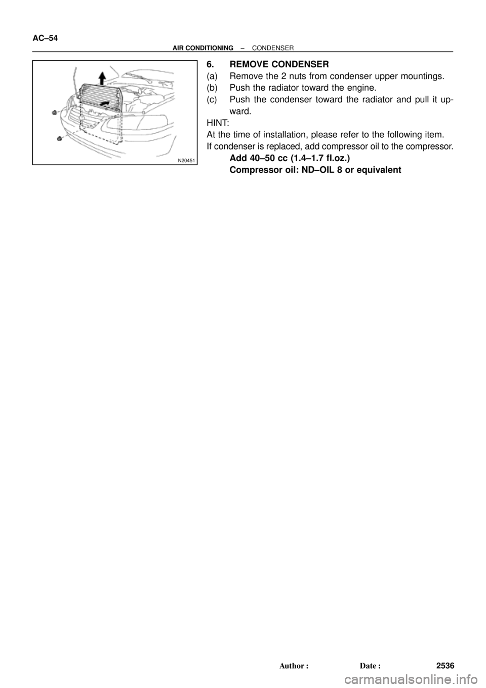
6. REMOVE CONDENSER
(a) Remove the 2 nuts from condenser upper mountings.
(b) Push the radiator toward the engine.
(c) Push the condenser toward the radiator and pull it up-
ward.
HINT:
At the time of installation, please refer to the following item.
If condenser is replaced, add compressor oil to the compressor.
Add 40±50 cc (1.4±1.7 fl.oz.)
Compressor oil: ND±OIL 8 or equivalent
Page 198 of 4592
AUTOMATIC TRANSAXLECOMPONENT PARTS REMOVAL ±
AX±28
DISASSEMBLY OF DIFFERENTIAL
1. REMOVE CARRIER COVER
2. MEASURE TOTAL PRELOAD
Using a torque meter, measure the total preload, and note
the measurement value.
3. MEASURE BACKLASH OF SIDE GEAR
Measure each side gear backlash while holding one pin-
ion toward the case.
Standard backlash:
0.05 ± 0.20 mm (0.0020 ± 0.0079 in.)
4. REMOVE LH BEARING RETAINER
(a) Remove the 6 bolts.
(b) Tap the retainer with a plastic hammer to remove it.
(c) Remove the O±ring from the retainer.
5. REMOVE RH SIDE BEARING CAP
Remove the 2 bolts and the side bearing cap.
AX0EX±02
Page 226 of 4592
AUTOMATIC TRANSAXLEREAR PLANETARY GEAR ±
AX±56
4. REMOVE ONE±WAY CLUTCH FROM OUTER RACE
(a) Remove the 2 snap rings and retainers from both sides.
(b) Remove the one±way clutch from the outer race.
REAR PLANETARY GEAR INSPECTION
MEASURE PLANETARY PINION GEAR THRUST
CLEARANCE
Using a feeler gauge, measure the planetary pinion gear
thrust clearance.
Standard clearance:
0.20 ± 0.50 mm (0.0079 ± 0.0197 in.)
ONE±WAY CLUTCH ASSEMBLY
1. INSTALL ONE±WAY CLUTCH
(a) Install the one±way clutch into the outer race, facing the
flanged side of the one±way clutch toward the shiny side
of the outer race.
(b) Install the 2 retainers and snap rings to both sides.
2. INSTALL PLANETARY GEAR INTO ONE±WAY
CLUTCH
Install the planetary gear into the one±way clutch, facing
the inner race of the planetary gear toward the black side
of the one±way clutch outer race.
AX0FR±02
AX0FS±02
Page 241 of 4592
AUTOMATIC TRANSAXLEOVERDRIVE UNIT ±
AX±71
8. ADJUST PRELOAD OF COUNTER DRIVE GEAR
(a) Place SST onto the adjusting nut and hold the shaft in a
vise with soft jaws.
SST 09350±32014 (09351±32080)
(b) Tighten the adjusting nut until the following gear starting
load occurs with a tension gauge.
Preload (at starting):
9 ± 15 N (920 ± 1,530 gf, 2.0 ± 3.4 lbf)
HINT: Turn the counter drive gear right and left several
times before measuring the preload.
(c) Lock the adjusting nut with one tab on locking washer.
Bend the locking washer tab until it is even with the adjust-
ing nut groove.
9. INSTALL PINION SHAFT PLUGS
Install the 4 plugs into the pinion shaft.
10. INSTALL NO.3 OVERDRIVE PLANETARY THRUST
WASHER
Install the thrust washer, facing the groove toward the ov-
erdrive case.
11. ASSEMBLE OVERDRIVE ONE±WAY CLUTCH
(a) Install the one±way clutch into the outer race.
(b) Install a retainer on both sides of the one±way clutch.
Page 260 of 4592
AUTOMATIC TRANSAXLEDIFFERENTIAL ASSEMBLY ±
AX±90
DIFFERENTIAL CASE DISASSEMBLY
1. REMOVE RING GEAR
(a) Loosen the staked part of the lock plate.
(b) Remove the 8 bolts and locking plates.
(c) Using a copper hammer, tap on the ring gear to remove
it from the case.
2. REMOVE SIDE BEARINGS
Fasten SST under the bearing above the cutouts on the
speedometer drive gear. Remove the bearing from the
case.
SST 09502±10012
3. CHECK SIDE GEAR BACKLASH
Using a dial gauge, measure the backlash of each side
gear while holding one pinion toward the case.
Standard backlash:
0.05 ± 0.20 mm (0.0020 ± 0.0079 in.)
4. DISASSEMBLE DIFFERENTIAL CASE
(a) Drive out the pinion shaft lock pin from the side on which
the ring gear is installed.
AX0GG±02
Page 263 of 4592
AUTOMATIC TRANSAXLEDIFFERENTIAL ASSEMBLY ±
AX±93
(d) Check the side gear backlash.
Measure the side gear backlash while holding one pinion
gear toward the case.
Standard backlash:
0.05 ± 0.20 mm (0.0020 ± 0.0079 in.)
Referring to the table below, select thrust washers which
will ensure that the backlash is within specification. Try to
select washers of the same size for both sides.
Thrust washer thickness
mm (in.)
ThicknessThickness
0.95 (0.0374)1.10 (0.0433)
1.00 (0.0394)1.15 (0.0453)
1.05 (0.0413)1.20 (0.0472)
If the backlash is not within specification, install a thrust
washer of a different thickness.
(e) Using a hammer and punch, drive the lock pin through the
case and hole in the pinion shaft.
(f) Stake the differential case.
5. INSTALL SIDE BEARINGS
(a) Install the speedometer drive gear onto the differential
case.
(b) Using SST and a press, press in the RH side bearing onto
the differential case.
SST 09350±32014 (09351±32090, 09351±32120)
Page 280 of 4592
 Install the overdrive unit with overdrive case to the trans-
axle case.
(f) Install and tighten the bolts.
Torque: 25 N´m (250 kgf´cm,")
AUTOMATIC TRANSAXLECOMPONENT PARTS INSTALLATION ±
AX±110
(e) Install the overdrive unit with overdrive case to the trans-
axle case.
(f) Install and tighten the bolts.
Torque: 25 N´m (250 kgf´cm, 18 ft´lbf)
9. CHECK INTERMEDIATE SHAFT END PLAY
(a) Make sure that the intermediate shaft has thrust play.
Thrust play:
0.49 ± 1.51 mm (0.0193 ± 0.0594 in.)
If the thrust play is not within specification, check the
installation of intermediate shaft.
(b) Make sure that the intermediate shaft turns smoothly.
10. INSTALL FIRST AND REVERSE BRAKE IN CASE
(a) Install the inner flange facing the flat end toward the oil
pump side.
(b) Install the discs and plates.
Install in order: P=Plate D=Disc
D ± P ± D ± P ± D ± P ± D ± P ± D ± P ± D
(c) Install the outer flange, facing the flat end toward the pis-
ton side.
11. INSTALL SNAP RING
Be sure the end gap of the snap ring is not aligned with
one of the cutouts.
12. CHECK OPERATION OF FIRST AND REVERSE
BRAKE
Apply compressed air into the oil passage with the case
and be sure that the piston moves.
Page 282 of 4592
AUTOMATIC TRANSAXLECOMPONENT PARTS INSTALLATION ±
AX±112
(c) Coat the thrust washer with petroleum jelly and install it
onto the planetary gear.
16. CHECK OPERATION OF NO.2 ONE±WAY CLUTCH
Turn the planetary carrier. The carrier should turn freely
clockwise and lock counterclockwise.
17. INSTALL SNAP RING
Be sure the end gap of the snap ring is not aligned with
one of cutouts.
18. INSTALL SECOND COAST BRAKE BAND GUIDE
Install the 2 band guides so that its tip touches the case.
19. INSTALL SECOND BRAKE INTO CASE
(a) Install the flange, facing the flat end toward the oil pump
side.
(b) Install the discs and plates.
Install in order: P=Plate D=Disc
Flange ± D ± P ± D ± P ± D ± P

 Remove the 2 snap rings and retainers from both sides.
(b) Remove the one±way clutch from the outer race")
 Place SST onto the adjusting nut and hold the shaft in a
vise with soft jaws.
SST 09350±32014 (09351±32080)
(b")
 Loosen the staked part of the lock plate.
(b) Remove the 8 bolts and locking plates.
(c) Using")
 Check the side gear backlash.
Measure the side gear backlash while holding one pinion
gear toward the case.
Standard backlash:
0.05 ± 0.20 mm (0")
 Coat the thrust washer with petroleum jelly and install it
onto the planetary gear.
16. CHECK OPERATION OF NO.2 ONE±WAY CLUTCH
Turn the")