Page 3754 of 4592
BRAKE DISC ANTI±RUST COVER REMOVAL (CONT'D)Page 2 of 2
RECOMMENDED REMOVAL PROCEDURE:
Turn the right front wheel to full right lock.
Unhook the Anti±Rust Cover from the disc brake dust cover, then pull the center of the Anti±Rust
Cover toward the wheel. This separates the Anti±Rust Cover from the disc brake dust cover (see
illustration below).
Pull the center of the Anti±Rust Cover by hand towards you to break the thin portion of cover.
Remove the Anti±Rust Cover along the arch of the wheel disc by shaking it up and down. If the
cover is torn while removing, check to see that no parts of the cover are left inside.
Turn the steering wheel to full left lock and perform the same steps on the left front wheel. If
applicable, also remove the Anti±Rust Covers on the rear brakes.
Indicate on the new car inspection sheet that the Anti±Rust Covers have been removed.
Page 3763 of 4592

Toyota Supports ASE CertificationPage 1 of 4
BR004±00
Title:
BRAKE PAD CLICKING NOISE
Models:
'90 ± '00 All Models
Technical Service
BULLETIN
October 20, 2000
A clicking type noise may be noticed when first applying the brakes after changing
vehicle travel direction (
Drive/Forward to Reverse, Reverse to Drive/Forward). This is a
normal noise caused by the required brake pad±to±caliper clearances. When the
direction of travel is changed, the brake pads may ªshiftº towards the new direction of
travel. When the brake pad contacts the caliper, a clicking noise may be heard.
To minimize this clicking noise, a disc brake caliper grease has been made available for
use during brake service/maintenance operations. Under normal usage conditions this
grease should be effective for a period of 6 months to 1 year.
�1990 ± 2000 model year Toyota vehicles, all models.
PREVIOUS PART NUMBERCURRENT PART NUMBERPART NAME
N/A08887±80609Disc Brake Caliper Grease (50 g tube)
OP CODEDESCRIPTIONTIMEOPNT1T2
N/ANot Applicable to Warranty ±±±±
BRAKES
Introduction
Applicable
Vehicles
Parts
Information
Warranty
Information
Page 3855 of 4592

REFINISHING REPLACEMENT BUMPER COVERS ± PA003-02June 14, 2002
Page 2 of 2
2.Scrub the bumper covers with the soap and water solution, making sure all
difficult±to±reach areas are thoroughly cleaned.
3. Rinse the entire bumper cover with clean deionized water, making sure all
difficult±to±reach areas are thoroughly rinsed.
4. Dry the surface with a clean towel before water dries on the surface. Clean, dry
compressed air from an oil±less compressor may be substituted for drying with a
towel.
5. Degrease the surface with a wax, grease, and silicone
remover.
NOTE:
Lacquer thinner or brake cleaner will NOT
remove silicone. You MUST use a wax,
grease, and silicone
remover. Carefully follow application instructions on the container
label. Fish eyes or other paint irregularities may result from not following instructions.
6. Apply a generous amount of sanding paste with a gray 3M� ScotchBrite pad. Only a
gray pad should be used during the sanding process. Sand the entire bumper cover
surface. Be sure all difficult±to±reach areas are thoroughly sanded.
7. Clean the entire bumper cover with car wash soap and water. Be sure all
difficult±to±reach areas are thoroughly cleaned.
8. Rinse the entire bumper with clean deionized water. Be sure all difficult±to±reach
areas are thoroughly rinsed.
9. Degrease the surface with an anti±static plastic parts cleaner
and a white body shop
towel or paper towel.
NOTE:
Never use a red shop towel to wipe the surface (contains silicone).
10. Assure the bumper is firmly held in place to a steady fixture.
11. Apply a plastic parts adhesion promoter to the surface, according to the
manufacturer 's recommendations.
12. Apply plastic parts primer to the surface, according to the paint manufacturer's
recommendations.
13. Since bumpers are made of flexible plastic urethane material, use a two±part
urethane finish paint system with plasticizer (flex agent) for all bumper and cladding
repairs. Apply the appropriate top coat to the surface, according to the paint
manufacturer 's recommendations.
14. If heat is applied to cure the paint, assure the surface temperature does not exceed
80�C (176�F. )
For additional information concerning the refinish process for plastic bumpers/cladding,
please contact your respective refinish paint manufacturer's local representative.
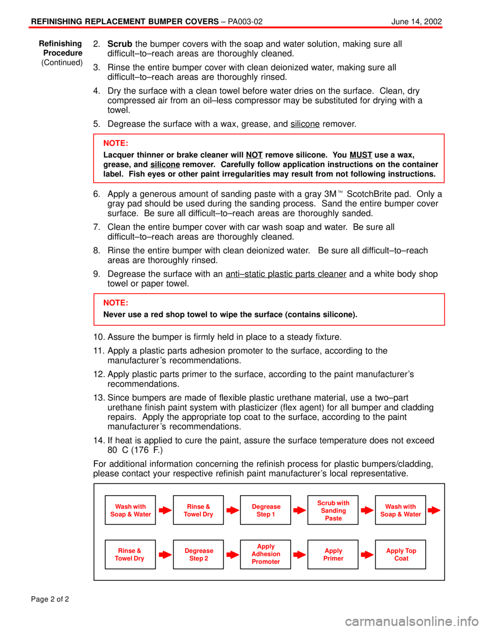
Apply
Primer
Wash with
Soap & WaterScrub with
Sanding
PasteWash with
Soap & WaterRinse &
Towel DryDegrease
Step 1
Apply
Adhesion
PromoterApply Top
CoatRinse &
Towel DryDegrease
Step 2
Refinishing
Procedure
(Continued)
Page 3944 of 4592

TSB
IntroductionTo prevent overheating of the transmission when towing a weight of more than 1,000
pounds, a transmission oil cooler should be installed. The transmission oil cooler and
required hardware for installation are available through normal parts supply.
Towing�Up to 2,000 pounds (with transmission cooler installed).
Capacity
Affected�1997 Camrys with A541E Automatic Transmissions.
Vehicles
Parts
Information
Warranty
Information
TRANSMISSION & CLUTCH
October 17, 1997
Title:
TRANSMISSION OIL COOLER INSTALLATION
Models:
'97 CAMRY WITH A541E ATM
Page 1 of 6
TC003±97
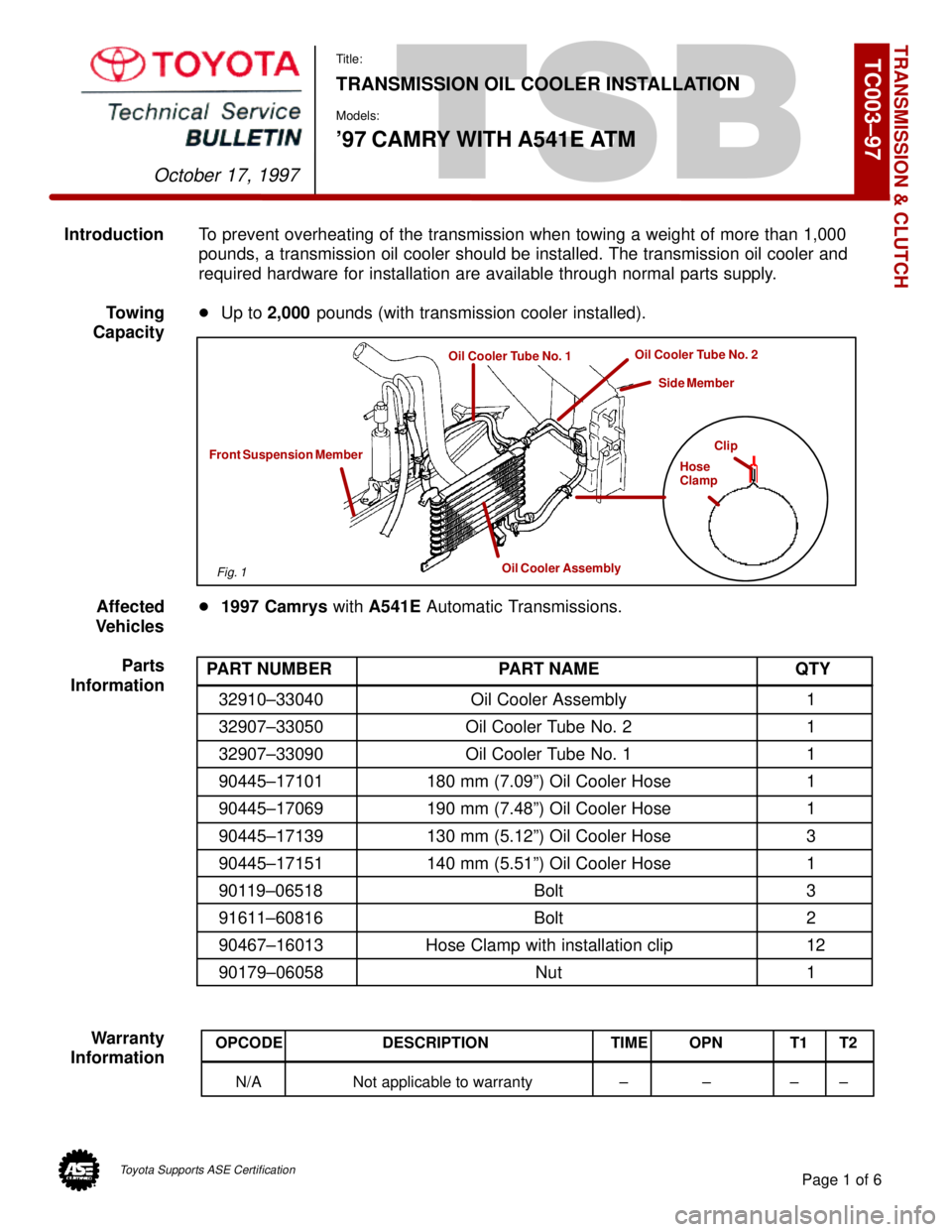
Clip
Hose
Clamp
Oil Cooler Assembly
Front Suspension Member
Oil Cooler Tube No. 1Oil Cooler Tube No. 2
Side Member
PART NUMBER PART NAME QTY
32910±33040 Oil Cooler Assembly 1
32907±33050 Oil Cooler Tube No. 2 1
32907±33090 Oil Cooler Tube No. 1 1
90445±17101 180 mm (7.09º) Oil Cooler Hose 1
90445±17069 190 mm (7.48º) Oil Cooler Hose 1
90445±17139 130 mm (5.12º) Oil Cooler Hose 3
90445±17151 140 mm (5.51º) Oil Cooler Hose 1
90119±06518 Bolt 3
91611±60816 Bolt 2
90467±16013 Hose Clamp with installation clip 12
90179±06058 Nut 1
OPCODE DESCRIPTION TIME OPN T1 T2
N/A Not applicable to warranty ± ± ± ±
Fig. 1
Toyota Supports ASE Certification
Page 4420 of 4592

Current is applied at all times through the POWER fuse to TERMINAL 5 of the power relay. With the ignition SW turned on,
the current flows through the GAUGE fuse to TERMINAL 7 of the integration relay to TERMINAL (A) 12 (w/o theft deterrent
system), (B) 3 (w/ theft deterrent system) to TERMINAL 1 of the power relay to TERMINAL 2 to GROUND, as a result, power
relay is activated and the current to TERMINAL 5 of the power relay flows from TERMINAL 3 of the power relay to
TERMINAL 4 of the moon roof control relay.
1. SLIDE OPEN OPERATION
Only when the slide open switch is valid and actuated the moon roof motor continually will operate towards the open
direction of the roof panel.
Releasing and again depressing the open switch, or depressing another operation switch shall cancel this express open
function. The relay shall only operate the moon roof motor continually for approx. 20 seconds per actuation.
2. SLIDE CLOSE OPERATION
Only when the tilt up switch is valid and actuated the moon roof motor will operate towards the close direction of the roof
panel.
When the moon roof reaches about 120 mm short of the fully closed position, the limit switch No.2 is turned from on to off.
Thereby signaling the moon roof control relay to stop the motor. The motor can not continue to operate until the close switch
is released and again depressed.
3. TILT UP OPERATION
Only when the tilt up switch is valid and actuated the moon roof motor will operate towards the closed direction of the roof
panel.
4. TILT DOWN OPERATION
Only when the slide open switch is valid and actuated the moon roof motor will operate towards the open direction of the roof
panel.
5. KEY OFF MOON ROOF OPERATION
With the ignition SW turned from on to off, the integration relay operates and current flows from the DOOR fuse to
TERMINAL (A) 13 (w/o theft deterrent system), (B) 1 (w/ theft deterrent system) of the relay to TERMINAL (A) 12 (w/o theft
deterrent system), (B) 3 (w/ theft deterrent system) to TERMINAL 1 of the power relay to TERMINAL 2 to GROUND for about
43 seconds. In the same way as normal operation, the current flows from the POWER fuse to TERMINAL 5 of the power
relay to TERMINAL 3 to TERMINAL 4 of the moon roof control relay. As a result, for about 43 seconds after the ignition SW
is turned off, the functioning of this relay makes it possible to open and close the moon roof. Also, by opening the front door
(Door courtesy SW on) within about 43 seconds after turning the ignition SW to off, a signal is input to TERMINALS 6 or (A) 8
(w/o theft deterrent system), (B) 6 (w/ theft deterrent system) of the integration relay. As a result, the relay turns off and open
close movement of the moon roof stops.
POWER RELAY [INSTRUMENT PANEL J/B]
5±3 : Closed with the ignition SW at ON position or key off moon roof operation
M3 MOON ROOF CONTROL SW AND RELAY
2±GROUND : Always continuity
4±GROUND : Approx. 12 volts with the ignition SW at ON position or key off moon roof operation
: PARTS LOCATION
CodeSee PageCodeSee PageCodeSee Page
D1232J1131M4A33
D1332J33A31M4B33
I18A30J34B31I18B30M333
SYSTEM OUTLINE
SERVICE HINTS