Page 3636 of 4592
SA1EA±02
N00191
F06526
BA
FA1615
Matchmarks
SA1443
Matchmarks
SA±8
± SUSPENSION AND AXLEFRONT DRIVE SHAFT
DISASSEMBLY
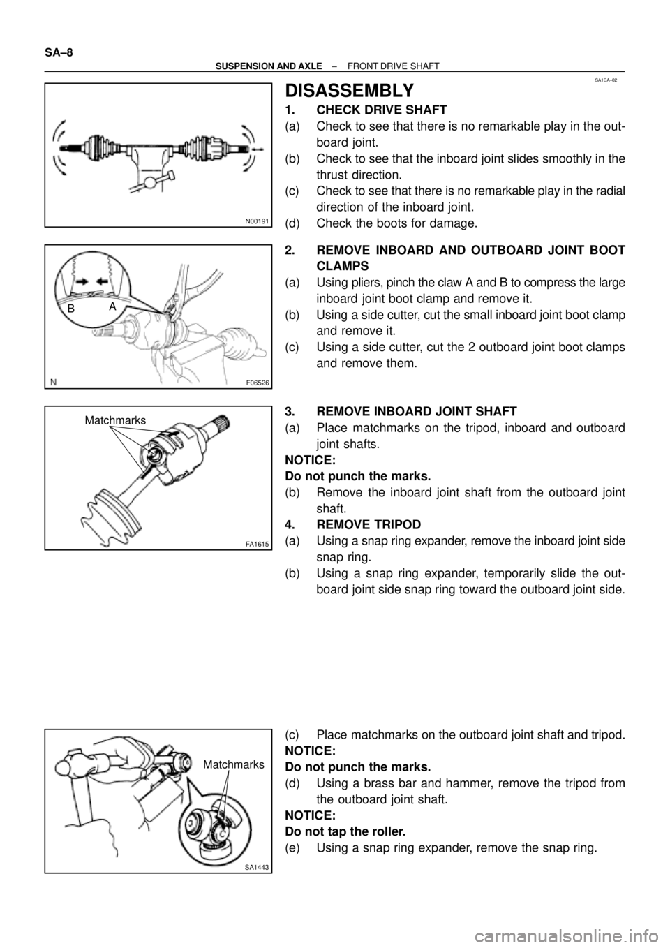
1. CHECK DRIVE SHAFT
(a) Check to see that there is no remarkable play in the out-
board joint.
(b) Check to see that the inboard joint slides smoothly in the
thrust direction.
(c) Check to see that there is no remarkable play in the radial
direction of the inboard joint.
(d) Check the boots for damage.
2. REMOVE INBOARD AND OUTBOARD JOINT BOOT
CLAMPS
(a) Using pliers, pinch the claw A and B to compress the large
inboard joint boot clamp and remove it.
(b) Using a side cutter, cut the small inboard joint boot clamp
and remove it.
(c) Using a side cutter, cut the 2 outboard joint boot clamps
and remove them.
3. REMOVE INBOARD JOINT SHAFT
(a) Place matchmarks on the tripod, inboard and outboard
joint shafts.
NOTICE:
Do not punch the marks.
(b) Remove the inboard joint shaft from the outboard joint
shaft.
4. REMOVE TRIPOD
(a) Using a snap ring expander, remove the inboard joint side
snap ring.
(b) Using a snap ring expander, temporarily slide the out-
board joint side snap ring toward the outboard joint side.
(c) Place matchmarks on the outboard joint shaft and tripod.
NOTICE:
Do not punch the marks.
(d) Using a brass bar and hammer, remove the tripod from
the outboard joint shaft.
NOTICE:
Do not tap the roller.
(e) Using a snap ring expander, remove the snap ring.
Page 3640 of 4592
F01747
Inboard Joint BootOutboard Joint Boot
Vinyl tape
R00764
SA±12
± SUSPENSION AND AXLEFRONT DRIVE SHAFT
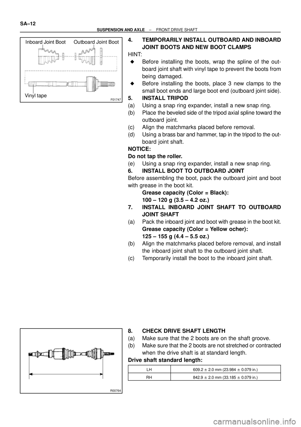
4. TEMPORARILY INSTALL OUTBOARD AND INBOARD
JOINT BOOTS AND NEW BOOT CLAMPS
HINT:
�Before installing the boots, wrap the spline of the out-
board joint shaft with vinyl tape to prevent the boots from
being damaged.
�Before installing the boots, place 3 new clamps to the
small boot ends and large boot end (outboard joint side).
5. INSTALL TRIPOD
(a) Using a snap ring expander, install a new snap ring.
(b) Place the beveled side of the tripod axial spline toward the
outboard joint.
(c) Align the matchmarks placed before removal.
(d) Using a brass bar and hammer, tap in the tripod to the out-
board joint shaft.
NOTICE:
Do not tap the roller.
(e) Using a snap ring expander, install a new snap ring.
6. INSTALL BOOT TO OUTBOARD JOINT
Before assembling the boot, pack the outboard joint and boot
with grease in the boot kit.
Grease capacity (Color = Black):
100 ± 120 g (3.5 ± 4.2 oz.)
7. INSTALL INBOARD JOINT SHAFT TO OUTBOARD
JOINT SHAFT
(a) Pack the inboard joint and boot with grease in the boot kit.
Grease capacity (Color = Yellow ocher):
125 ± 155 g (4.4 ± 5.5 oz.)
(b) Align the matchmarks placed before removal, and install
the inboard joint shaft to the outboard joint shaft.
(c) Temporarily install the boot to the inboard joint shaft.
8. CHECK DRIVE SHAFT LENGTH
(a) Make sure that the 2 boots are on the shaft groove.
(b) Make sure that the 2 boots are not stretched or contracted
when the drive shaft is at standard length.
Drive shaft standard length:
LH609.2 ± 2.0 mm (23.984 ± 0.079 in.)
RH842.9 ± 2.0 mm (33.185 ± 0.079 in.)
Page 3659 of 4592
Toyota Supports ASE CertificationPage 1 of 2
AX001±00Title:
TOYOTA DINGHY" TOWING GUIDE
Models:
All Models
Technical Service
BULLETIN
March 17, 2000
The chart on the next page indicates which Toyota vehicles can be Dinghy towed (towed
with four wheels on the ground) behind a Motorhome.
CAUTION:
Dinghy towing a vehicle behind a Motorhome requires special towing equipment
and accessories. Please see your Motorhome Manufacturer / Service Outlet for
recommended towing equipment.
OP CODEDESCRIPTIONTIMEOPNT1T2
N/ANot Applicable to Warranty ±±±±
ACCESSORIES
Introduction
Warranty
Information
Page 3660 of 4592
TOYOTA ªDINGHYº TOWING GUIDE ± AX001±00 March 17, 2000
Page 2 of 2
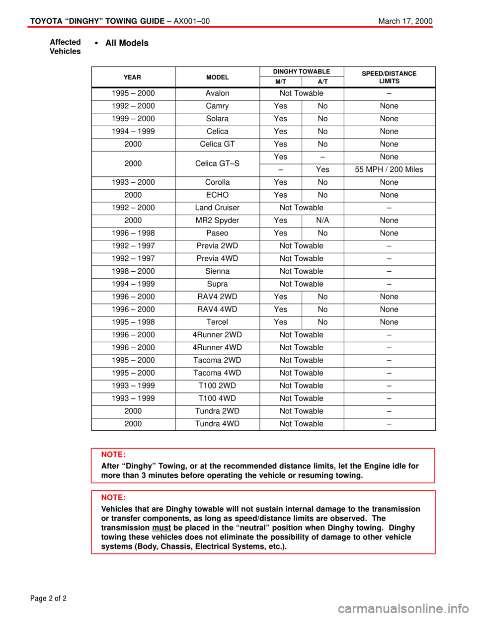
�All Models
YEARMODELDINGHY TOWABLESPEED/DISTANCEYEARMODELM/TA/T
SPEED/DISTANCELIMITS
1995 ± 2000AvalonNot Towable±
1992 ± 2000CamryYesNoNone
1999 ± 2000SolaraYesNoNone
1994 ± 1999CelicaYesNoNone
2000Celica GTYesNoNone
2000Celica GT±SYes±None2000Celica GT±S±Yes55 MPH / 200 Miles
1993 ± 2000CorollaYesNoNone
2000ECHOYesNoNone
1992 ± 2000Land CruiserNot Towable±
2000MR2 SpyderYesN/ANone
1996 ± 1998PaseoYesNoNone
1992 ± 1997Previa 2WDNot Towable±
1992 ± 1997Previa 4WDNot Towable±
1998 ± 2000SiennaNot Towable±
1994 ± 1999SupraNot Towable±
1996 ± 2000RAV4 2WDYesNoNone
1996 ± 2000RAV4 4WDYesNoNone
1995 ± 1998TercelYesNoNone
1996 ± 20004Runner 2WDNot Towable±
1996 ± 20004Runner 4WDNot Towable±
1995 ± 2000Tacoma 2WDNot Towable±
1995 ± 2000Tacoma 4WDNot Towable±
1993 ± 1999T100 2WDNot Towable±
1993 ± 1999T100 4WDNot Towable±
2000Tundra 2WDNot Towable±
2000Tundra 4WDNot Towable±
NOTE:
After ªDinghyº Towing, or at the recommended distance limits, let the Engine idle for
more than 3 minutes before operating the vehicle or resuming towing.
NOTE:
Vehicles that are Dinghy towable will not sustain internal damage to the transmission
or transfer components, as long as speed/distance limits are observed. The
transmission must
be placed in the ªneutralº position when Dinghy towing. Dinghy
towing these vehicles does not eliminate the possibility of damage to other vehicle
systems (Body, Chassis, Electrical Systems, etc.). Affected
Vehicles
Page 3664 of 4592
Toyota Supports ASE CertificationPage 1 of 1
AX004±99Title:
TOYOTA DINGHY" TOWING GUIDE
Models:
All Models
Technical Service
BULLETIN
March 19, 1999
The following chart indicates which Toyota vehicles can be Dinghy towed (towed with four
wheels on the ground) behind a Motorhome.
CAUTION:
Dinghy towing a vehicle behind a Motorhome requires special towing equipment and
accessories. Please see your Motorhome Manufacturer / Service Outlet for
recommended towing equipment.
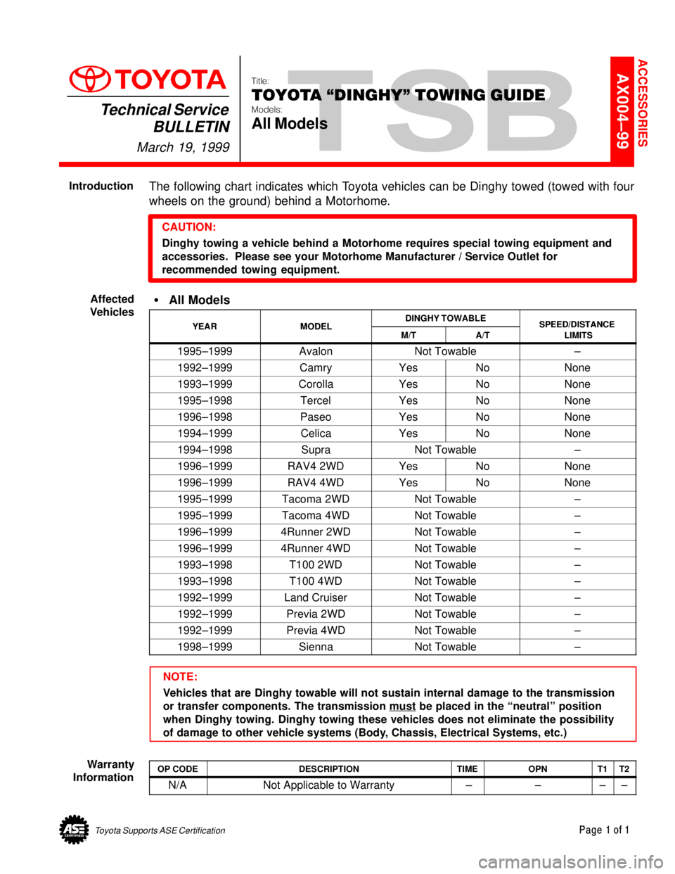
�All Models
YEARMODELDINGHY TOWABLESPEED/DISTANCEYEARMODELM/TA/TSPEED/DISTANCE
LIMITS
1995±1999AvalonNot Towable±
1992±1999CamryYesNoNone
1993±1999CorollaYesNoNone
1995±1998TercelYesNoNone
1996±1998PaseoYesNoNone
1994±1999CelicaYesNoNone
1994±1998SupraNot Towable±
1996±1999RAV4 2WDYesNoNone
1996±1999RAV4 4WDYesNoNone
1995±1999Tacoma 2WDNot Towable±
1995±1999Tacoma 4WDNot Towable±
1996±19994Runner 2WDNot Towable±
1996±19994Runner 4WDNot Towable±
1993±1998T100 2WDNot Towable±
1993±1998T100 4WDNot Towable±
1992±1999Land CruiserNot Towable±
1992±1999Previa 2WDNot Towable±
1992±1999Previa 4WDNot Towable±
1998±1999SiennaNot Towable±
NOTE:
Vehicles that are Dinghy towable will not sustain internal damage to the transmission
or transfer components. The transmission must
be placed in the ªneutralº position
when Dinghy towing. Dinghy towing these vehicles does not eliminate the possibility
of damage to other vehicle systems (Body, Chassis, Electrical Systems, etc.)
OP CODEDESCRIPTIONTIMEOPNT1T2
N/ANot Applicable to Warranty ±±±±
ACCESSORIES
Introduction
Affected
Vehicles
Warranty
Information
Page 3713 of 4592
POWER SEAT MOTOR CABLE REPAIR TIP ± BO017-01 Revised May 25, 2001
Page 2 of 2
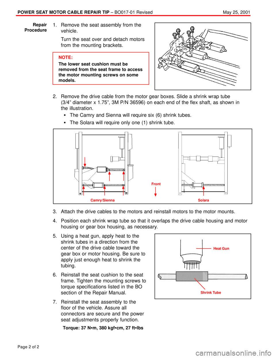
1. Remove the seat assembly from the
vehicle.
Turn the seat over and detach motors
from the mounting brackets.
NOTE:
The lower seat cushion must be
removed from the seat frame to access
the motor mounting screws on some
models.
2. Remove the drive cable from the motor gear boxes. Slide a shrink wrap tube
(3/4º diameter x 1.75º, 3M P/N 36596) on each end of the flex shaft, as shown in
the illustration.
�The Camry and Sienna will require six (6) shrink tubes.
�The Solara will require only one (1) shrink tube.
Camry/Sienna Solara
Front
3. Attach the drive cables to the motors and reinstall motors to the motor mounts.
4. Position each shrink wrap tube so that it overlaps the drive cable housing and motor
housing or gear box housing, as necessary.
5. Using a heat gun, apply heat to the
shrink tubes in a direction from the
center of the drive cable toward the
gear box or motor housing. Be sure to
apply just enough heat to shrink the
tubing.
6. Reinstall the seat cushion to the seat
frame. Tighten the mounting screws to
torque specifications listed in the BO
section of the Repair Manual.
7. Reinstall the seat assembly to the
floor of the vehicle. Assure all
connectors are secure and the power
seat adjustments properly function.
Torque: 37 N�m, 380 kgf�cm, 27 ft�lbs
Repair
Procedure
Heat Gun
Shrink Tube
Page 3716 of 4592
DOOR GLASS DISPLACEMENT ± BO017±99 November 26, 1999
Page 2 of 2
1. Lower the door glass, disconnect the power window switch, remove the front door
trim panel, speaker, and loosen the door mirror mounts to gain access to the door
glass and lower frames. Remove the front lower frame (2 screws).
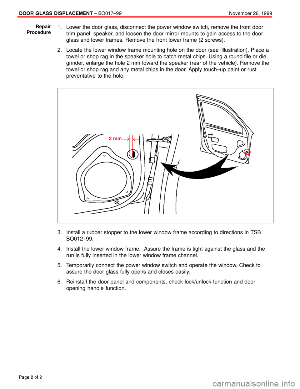
2. Locate the lower window frame mounting hole on the door (see illlustration). Place a
towel or shop rag in the speaker hole to catch metal chips. Using a round file or die
grinder, enlarge the hole 2 mm toward the speaker (rear of the vehicle). Remove the
towel or shop rag and any metal chips in the door. Apply touch±up paint or rust
preventative to the hole.
2 mm"u
3. Install a rubber stopper to the lower window frame according to directions in TSB
BO012±99.
4. Install the lower window frame. Assure the frame is tight against the glass and the
run is fully inserted in the lower window frame channel.
5. Temporarily connect the power window switch and operate the window. Check to
assure the door glass fully opens and closes easily.
6. Reinstall the door panel and components, check lock/unlock function and door
opening handle function.
Repair
Procedure
Page 3751 of 4592
Toyota Supports ASE CertificationPage 1 of 2
BO030-01Title:
WINDSHIELD WIPER BLADE
MAINTENANCE AND CLEANING
Models:
All Models
Technical Service
BULLETIN
December 7, 2001
The following procedures are recommended to maintain windshield wiper blade
performance.
�All models.
OP CODEDESCRIPTIONTIMEOPNT1T2
N/ANot Applicable to Warranty±±±±
Recommendations for Windshield Wiper Maintenance, Cleaning and Use:
1. Scheduled Maintenance
�Check wiper rubber blades every 4 ± 6 months or 7,500 miles for wear, cracking
and contamination.
�Clean glass and rubber wiper blades if blades are not clearing glass adequately.
If this does not correct the problem, then replace the rubber elements.
2. Cleaning Procedure
�Wiper Rubber: Bugs, dirt, sap and road grime on blades will cause streaking.
Clean wiper rubber of road and environmental debris using cloth or paper towel
soaked with windshield washer fluid or mild detergent.
�DO NOT USE fuel, kerosene, or petroleum based products to clean rubber wiper
blades.
�Windshield: Bugs, road grime, sap and car wash wax treatments decrease wiper
performance.
�Rinse windshield with water and apply non±abrasive cleaner, such as Bon±Ami
(www.faultless.com), with a sponge.
NOTE:
Make sure to use plenty of water with all powder based cleaners so the glass is
not scratched.
BODY
Introduction
Applicable
Vehicles
Warranty
Information
Maintenance,
Cleaning
and Use