Page 547 of 4592
 Check the side gear backlash.
Measure the side gear backlash while holding one pinion
gear toward the case.
Standard backlash:
0.05±0.20 mm (0.0")
AUTOMATIC TRANSAXLEDIFFERENTIAL ASSEMBLY ±
AX±98
(d) Check the side gear backlash.
Measure the side gear backlash while holding one pinion
gear toward the case.
Standard backlash:
0.05±0.20 mm (0.0020±0.0079 in.)
Refering to the table below, select thrust washers which
will ensure that the backlash is within specification. Try to
select washers of the same size for both sides.
Thrust washer thickness
mm (in.)
Thickness mm (in.)Thickness mm (in.)
1.60 (0.0630)1.70 (0.0670)
1.80 (0.0709)
If the backlash is not within specification, install a thrust
washer of a different thickness.
(e) Using a pin punch and hammer, drive the lock pin through
the case and hole in the pinion shaft.
(f) Stake the differential case.
2. INSTALL RING GEAR
(a) Clean the contact surface of the differential case.
(b) Heat the ring gear to about 100°C (212°F) in an oil bath.
NOTICE: Do not heat the ring gear above 110°C (230°F).
(c) Carefully remove the ring gear from the oil bath.
(d) Clean the contact surface of the ring gear with cleaning
solvent.
(e) Quickly install the ring gear on the differential case.
Install the 12 bolts.
HINT: Align the matchmarks on the differential left case
and contact the ring gear.
(f) Tighten the set bolts uniformly a little at a time.
Torque the bolts.
Torque: 124 N´m (1,260 kgf´cm, 91 ft´lbf)
Page 567 of 4592
AUTOMATIC TRANSAXLECOMPONENT PARTS INSTALLATION ±
AX±118
(b) Coat the bearing with petroleum jelly and install it onto the
front side of the forward clutch.
HINT: There are 2 different thickness bearings for adjust-
ment of the input shaft thrust play.
Bearing thickness
mm (in.)
ThicknessOuter diameterInner diameter
3.60 (0.1417)45.9 (1.807)27.7 (1.091)
4.19 (0.1650)47.1 (1.854)27.7 (1.091)
(c) Coat the thrust washer with petroleum jelly and install it
with the oil groove facing upward onto the direct clutch
drum.
(d) Mesh the hub of the forward clutch flukes with the direct
clutch discs.
HINT: Be careful that the bearing and thrust washer do not
get out of place.
(e) Install the direct clutch and forward clutch into the case.
HINT: Hold the direct clutch toward the forward clutch to
prevent the thrust washer from getting out of place.
25. INSTALL OIL PUMP INTO CASE
(a) Coat a new O±ring with ATF and install it to the oil pump.
Page 629 of 4592
 Compare the")
N20160
Ignition
Switch
Fuel
Gauge
Battery
Z05727
Ignition
SwitchFuel
Gauge
Battery
Ie±5±1±A BE1206123
45
N20212
A
B
C BE±48
± BODY ELECTRICALCOMBINATION METER
2268 Author�: Date�:
(b) Compare the tester with tachometer indications.
DC 13.5 V 25°C at (77 °F)
Standard indicationAllowable range
700630 ± 770
1,000900 ± 1,100
2,0001,850 ± 2,150
3,0002,800 ± 3,200
4,0003,800 ± 4,200
5,0004,800 ± 5,200
6,0005,750 ± 6,250
7,0006,700 ± 7,300
4. INSPECT FUEL RECEIVER GAUGE OPERATION
(a) Disconnect the connector from the sender gauge.
(b) Turn the ignition switch ON, check that the receiver gauge
needle indicates EMPTY.
(c) Connect terminals 2 and 3 on the wire harness side con-
nector through a 3.4±W test bulb.
(d) Turn the ignition switch ON, check that the bulb lights up
and the receiver gauge needle moves towards the full
side.
HINT:
Because of the silicon oil in the gauge, it will take a short time
for needle to stabilize.
If operation is not as specified, inspect the receiver gauge resis-
tance.
5. INSPECT FUEL RECEIVER GAUGE RESISTANCE
Measure the resistance between terminals.
Tester connectionResistance (W)
A ± BApprox. 126.2
A ± CApprox. 280.5
B ± CApprox. 154.3
If resistance value is not as specified, replace the receiver
gauge.
Page 638 of 4592

N21371
6
4
BE4029
Tester Probe
Tin FoilHeat Wire
BE0123
At Center
BE0124
0 VoltSeveral
Volts
Broken
Wire
± BODY ELECTRICALDEFOGGER SYSTEM
BE±57
2277 Author�: Date�:
5. w/ Heater:
INSPECT MIRROR DEFOGGER
(a) Connect the positive (+) lead from the battery to terminal
4 and the negative (±) lead to terminal 6.
(b) Check that the mirror becomes warm.
HINT:
It takes short time for the mirror to become warm.
6. INSPECT DEFOGGER WIRE
NOTICE:
�When cleaning the glass, use a soft, dry cloth, and
wipe the glass in the direction of the wire. Take care
not to damage the wires.
�Do not use detergents or glass cleaners with abrasive
ingredients.
�When measuring voltage, wind a piece of tin foil
around the top of the negative probe and press the foil
against the wire with your finger, as shown.
(a) Turn the ignition switch ON.
(b) Turn the defogger switch ON.
(c) Inspect the voltage at the center of each heat wire, as
shown.
VoltageCriteria
Approx. 5VOkay (No break in wire)
Approx.10V or 0VBroken wire
HINT:
If there is approximately 10 V, the wire is broken between the
center of the wire and the positive (+) end. If there is no voltage,
the wire is broken between the center of the wire and ground.
(d) Place the voltmeter positive (+) lead against the defogger
positive (+) terminal.
(e) Place the voltmeter negative (±) lead with the foil strip
against the heat wire at the positive (+) terminal end and
slide it toward the negative (±) terminal end.
(f) The point where the voltmeter deflects from zero to sever-
al V is the place where the heat wire is broken.
HINT:
If the heat wire is not broken, the voltmeter indicates 0 V at the
positive (+) end of the heat wire but gradually increases to about
12 V as the meter probe is moved to the other end.
Page 714 of 4592

BE16U±01
I12031
Ignition
Switch
Fuel
Gauge
BatteryECM
I12029
Ignition
SwitchFuel Gauge
BatteryWire Harness Side
N20212
A
B
C
I12030
BatteryWarning Light
Ignition
Switch
Wire Harness Side
± BODY ELECTRICALCOMBINATION METER
BE±5
INSPECTION
1. INSPECT FUEL RECEIVER GAUGE OPERATION
(a) Disconnect the connector from the ECM.
(b) Turn the ignition switch ON, check that the receiver gauge
needle indicates EMPTY.
(c) Connect terminals 2 on the wire harness side connector
through a 3.4±W test bulb.
(d) Turn the ignition switch ON, check that the bulb lights up
and the receiver gauge needle moves towards the full
side.
HINT:
Because of the silicon oil in the gauge, it will take a short time
for needle to stabilize.
If operation is not as specified, inspect the receiver gauge resis-
tance.
2. INSPECT FUEL RECEIVER GAUGE RESISTANCE
Measure the resistance between terminals.
Tester connectionResistance (W)
A ± BApprox. 270.1
A ± CApprox. 141.3
B ± CApprox. 128.8
If resistance value is not as specified, replace the receiver
gauge.
3. INSPECT FUEL SENDER GAUGE RESISTANCE
(See page SF±36)
4. INSPECT FUEL LEVEL WARNING LIGHT
(a) Disconnect the connector from the sender gauge.
(b) Connect terminals 8 on the wire harness side connector.
(c) Turn the ignition switch ON, check that the warning light
lights up.
If the warning light does not light up, test the bulb or inspect wire
harness.
5. INSPECT FUEL LEVEL WARNING SWITCH
(See page SF±40)
Page 764 of 4592
 Compare the")
N20160
Ignition
Switch
Fuel
Gauge
Battery
Z05727
Ignition
SwitchFuel
Gauge
Battery
Ie±5±1±A BE1206123
45
N20212
A
B
C BE±48
± BODY ELECTRICALCOMBINATION METER
2268 Author�: Date�:
(b) Compare the tester with tachometer indications.
DC 13.5 V 25°C at (77 °F)
Standard indicationAllowable range
700630 ± 770
1,000900 ± 1,100
2,0001,850 ± 2,150
3,0002,800 ± 3,200
4,0003,800 ± 4,200
5,0004,800 ± 5,200
6,0005,750 ± 6,250
7,0006,700 ± 7,300
4. INSPECT FUEL RECEIVER GAUGE OPERATION
(a) Disconnect the connector from the sender gauge.
(b) Turn the ignition switch ON, check that the receiver gauge
needle indicates EMPTY.
(c) Connect terminals 2 and 3 on the wire harness side con-
nector through a 3.4±W test bulb.
(d) Turn the ignition switch ON, check that the bulb lights up
and the receiver gauge needle moves towards the full
side.
HINT:
Because of the silicon oil in the gauge, it will take a short time
for needle to stabilize.
If operation is not as specified, inspect the receiver gauge resis-
tance.
5. INSPECT FUEL RECEIVER GAUGE RESISTANCE
Measure the resistance between terminals.
Tester connectionResistance (W)
A ± BApprox. 126.2
A ± CApprox. 280.5
B ± CApprox. 154.3
If resistance value is not as specified, replace the receiver
gauge.
Page 773 of 4592

N21371
6
4
BE4029
Tester Probe
Tin FoilHeat Wire
BE0123
At Center
BE0124
0 VoltSeveral
Volts
Broken
Wire
± BODY ELECTRICALDEFOGGER SYSTEM
BE±57
2277 Author�: Date�:
5. w/ Heater:
INSPECT MIRROR DEFOGGER
(a) Connect the positive (+) lead from the battery to terminal
4 and the negative (±) lead to terminal 6.
(b) Check that the mirror becomes warm.
HINT:
It takes short time for the mirror to become warm.
6. INSPECT DEFOGGER WIRE
NOTICE:
�When cleaning the glass, use a soft, dry cloth, and
wipe the glass in the direction of the wire. Take care
not to damage the wires.
�Do not use detergents or glass cleaners with abrasive
ingredients.
�When measuring voltage, wind a piece of tin foil
around the top of the negative probe and press the foil
against the wire with your finger, as shown.
(a) Turn the ignition switch ON.
(b) Turn the defogger switch ON.
(c) Inspect the voltage at the center of each heat wire, as
shown.
VoltageCriteria
Approx. 5VOkay (No break in wire)
Approx.10V or 0VBroken wire
HINT:
If there is approximately 10 V, the wire is broken between the
center of the wire and the positive (+) end. If there is no voltage,
the wire is broken between the center of the wire and ground.
(d) Place the voltmeter positive (+) lead against the defogger
positive (+) terminal.
(e) Place the voltmeter negative (±) lead with the foil strip
against the heat wire at the positive (+) terminal end and
slide it toward the negative (±) terminal end.
(f) The point where the voltmeter deflects from zero to sever-
al V is the place where the heat wire is broken.
HINT:
If the heat wire is not broken, the voltmeter indicates 0 V at the
positive (+) end of the heat wire but gradually increases to about
12 V as the meter probe is moved to the other end.
Page 869 of 4592
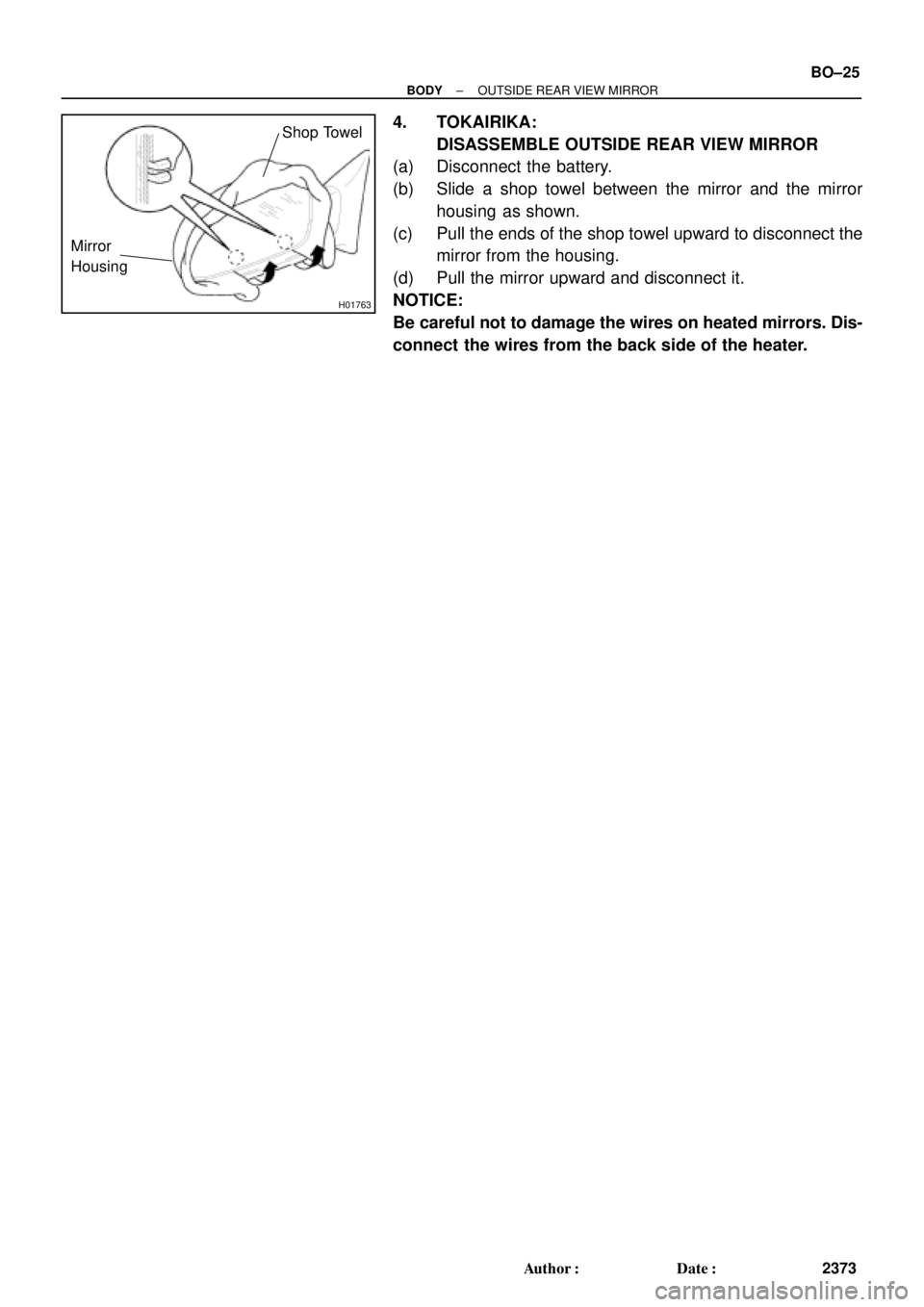
H01763
Mirror
Housing
Shop Towel
± BODYOUTSIDE REAR VIEW MIRROR
BO±25
2373 Author�: Date�:
4. TOKAIRIKA:
DISASSEMBLE OUTSIDE REAR VIEW MIRROR
(a) Disconnect the battery.
(b) Slide a shop towel between the mirror and the mirror
housing as shown.
(c) Pull the ends of the shop towel upward to disconnect the
mirror from the housing.
(d) Pull the mirror upward and disconnect it.
NOTICE:
Be careful not to damage the wires on heated mirrors. Dis-
connect the wires from the back side of the heater.
 Coat the bearing with petroleum jelly and install it onto the
front side of the forward clutch.
HINT: There are 2 different thickness bea")