Page 3219 of 4592
RS01P±14
H06728
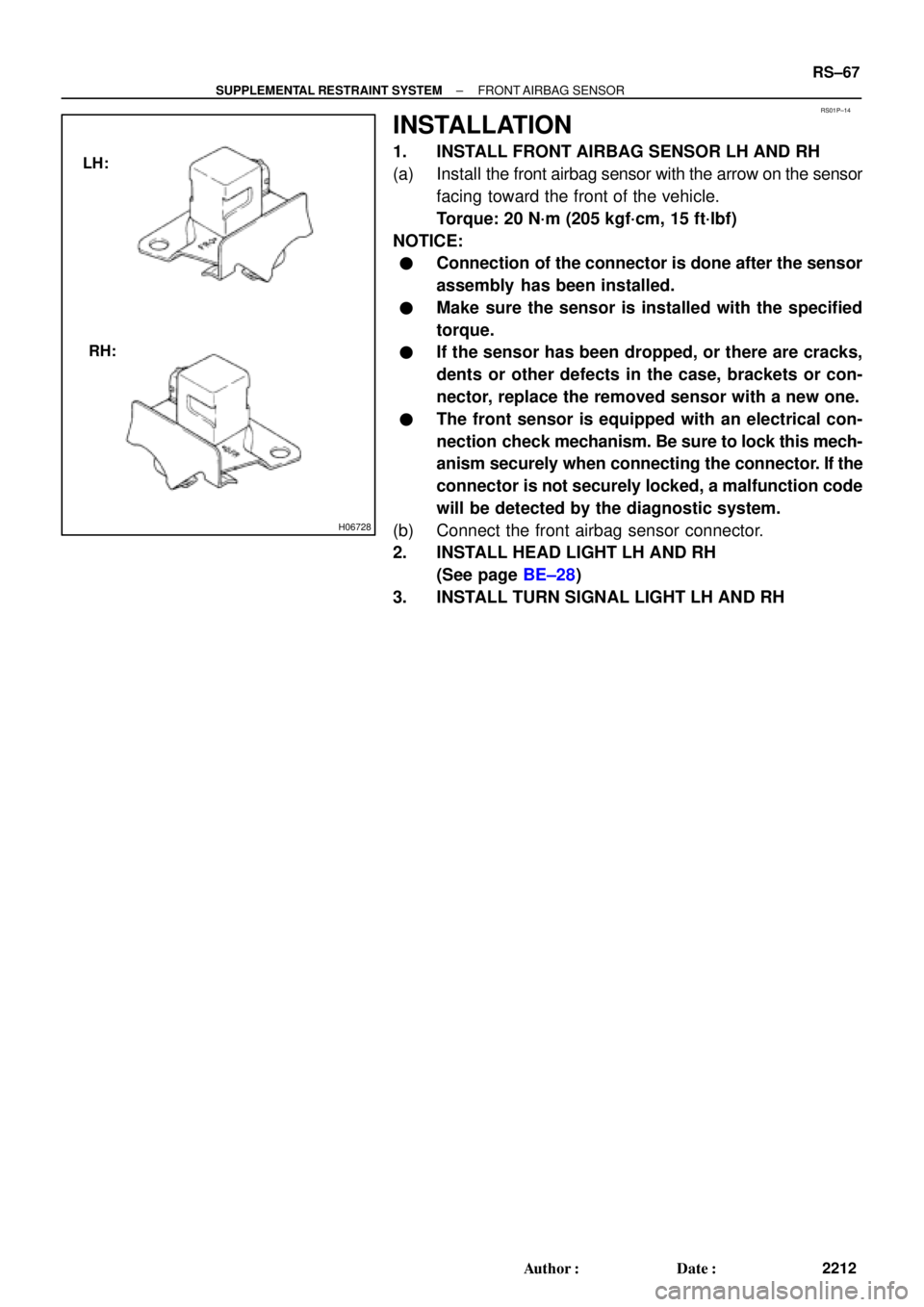
LH:
RH:
± SUPPLEMENTAL RESTRAINT SYSTEMFRONT AIRBAG SENSOR
RS±67
2212 Author�: Date�:
INSTALLATION
1. INSTALL FRONT AIRBAG SENSOR LH AND RH
(a) Install the front airbag sensor with the arrow on the sensor
facing toward the front of the vehicle.
Torque: 20 N´m (205 kgf´cm, 15 ft´lbf)
NOTICE:
�Connection of the connector is done after the sensor
assembly has been installed.
�Make sure the sensor is installed with the specified
torque.
�If the sensor has been dropped, or there are cracks,
dents or other defects in the case, brackets or con-
nector, replace the removed sensor with a new one.
�The front sensor is equipped with an electrical con-
nection check mechanism. Be sure to lock this mech-
anism securely when connecting the connector. If the
connector is not securely locked, a malfunction code
will be detected by the diagnostic system.
(b) Connect the front airbag sensor connector.
2. INSTALL HEAD LIGHT LH AND RH
(See page BE±28)
3. INSTALL TURN SIGNAL LIGHT LH AND RH
Page 3297 of 4592

SS04W±01
± SERVICE SPECIFICATIONSSUSPENSION AND AXLE
SS±59
222 Author�: Date�:
SUSPENSION AND AXLE
SERVICE DATA
P195/70R14 90SFront, Rear*1210 kPa (2.1 kgf/cm2, 30 psi)
Cold tire inflationP195/70R14 90SFront, Rear*2210 kPa (2.1 kgf/cm2, 30 psi)pressure
(Normal driving)P205/65R15 92HFront, Rear*1220 kPa (2.2 kgf/cm2, 32 psi)(Normal driving)P205/65R15 92HFront, Rear*2200 kPa (2.0 kgf/cm2, 29 psi)
P195/70R14 90SFront, Rear*3210 kPa (2.1 kgf/cm2, 30 psi)
Cold tire inflationP195/70R14 90SFront, Rear*4240 kPa (2.4 kgf/cm2, 35 psi)pressure
(Trailer towing)P205/65R15 92HFront, Rear*3220 kPa (2.2 kgf/cm2, 32 psi)(Trailer towing)P205/65R15 92HFront, Rear*4240 kPa (2.4 kgf/cm2, 35 psi)
V hi l h i ht 195/70R14Front*5212 mm (8.35 in.)Vehicle height195/70R14Rear*6264 mm (10.39 in.)
205/65R15Front*5215 mm (8.46 in.)205/65R15Rear*6266 mm (10.49 in.)
Camber 5S±FE±0°36'±45'(0.6°±0.75°)Camber 5S ± FE
1MZ ± FE
±036 ± 45 (0.6 ± 0.75)
±0°37' ± 45' (0.62° ± 0.75°)1MZ ± FE±037 ± 45 (0.62 ± 0.75)
Left ± right error45' (0.75°) or less
Front wheel
alignment
Caster 5S ± FE
1MZ ± FE
Left ± right error2°10' ± 45' (2.17° ± 0.75°)
2°11' ± 45' (2.18° ± 0.75°)
45' (0.75°) or less
alignmentSteering axis inclination 5S ± FE
1MZ ± FE
Left ± right error13°01' ± 45' (13.02° ± 0.75°)
13°04' ± 45' (13.07° ± 0.75°)
45' (0.75°) or less
Toe±in (Total)
Rack end length difference0° ± 12' (0° ± 0.2°)
0 ± 2 mm (0 ± 0.08 in.)
1.5 mm (0.059 in.) or less
Wh l l 195/70R14Inside wheel 37°12' ± 2° (37.2° ± 2°)Wheel angle195/70R14Outside wheel 32°21' (32.45°)
205/65R15Inside wheel 35°47' ± 2° (35.78° ± 2°)205/65R15Outside wheel 31°25' (31.42°)
Rear wheel
li t
Camber 5S ± FE
1MZ ± FE
Left ± right error±0°42' ± 45' (±0.7° ± 0.75°)
±0°45' ± 45' (±0.75° ± 0.75°)
45' (0.75°) or less
alignmentToe±in (Total)
No.2 lower suspension arm length difference0°24' ± 12' (0.4° ± 0.2°)
4 ± 2 mm (0.16 ± 0.08 in.)
1 mm (0.04 in.) or less
*1: For all loads including rated loads
*2: For reduced loads (1 to 4 passengers)
*3: For driving under 160 km/h (100 mph)
*4: For driving at 160 km/h (100 mph) or over
*5: Front measuring point
Measure from the ground to the center of the front side lower suspension arm mounting bolt.
*6: Rear measuring point
Measure from the ground to the center of the strut rod mounting bolt.
Page 3328 of 4592
S05331
SF0D7±03
S05327
Fuel Inlet Hose
S05522
SF±6
± SFI (5S±FE)FUEL PUMP
1439 Author�: Date�:
FUEL PUMP
ON±VEHICLE INSPECTION
1. CHECK FUEL PUMP OPERATION
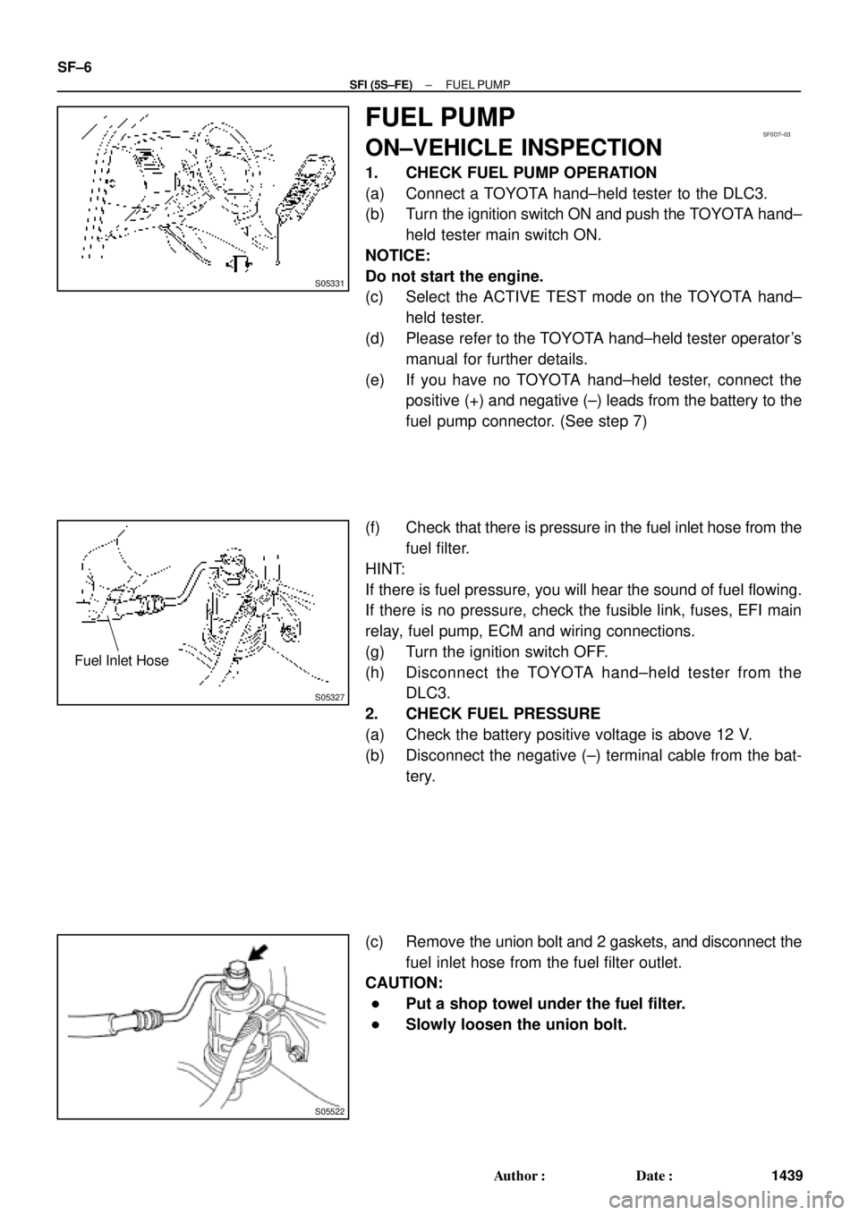
(a) Connect a TOYOTA hand±held tester to the DLC3.
(b) Turn the ignition switch ON and push the TOYOTA hand±
held tester main switch ON.
NOTICE:
Do not start the engine.
(c) Select the ACTIVE TEST mode on the TOYOTA hand±
held tester.
(d) Please refer to the TOYOTA hand±held tester operator's
manual for further details.
(e) If you have no TOYOTA hand±held tester, connect the
positive (+) and negative (±) leads from the battery to the
fuel pump connector. (See step 7)
(f) Check that there is pressure in the fuel inlet hose from the
fuel filter.
HINT:
If there is fuel pressure, you will hear the sound of fuel flowing.
If there is no pressure, check the fusible link, fuses, EFI main
relay, fuel pump, ECM and wiring connections.
(g) Turn the ignition switch OFF.
(h) Disconnect the TOYOTA hand±held tester from the
DLC3.
2. CHECK FUEL PRESSURE
(a) Check the battery positive voltage is above 12 V.
(b) Disconnect the negative (±) terminal cable from the bat-
tery.
(c) Remove the union bolt and 2 gaskets, and disconnect the
fuel inlet hose from the fuel filter outlet.
CAUTION:
�Put a shop towel under the fuel filter.
�Slowly loosen the union bolt.
Page 3558 of 4592
R03031
SA078±01
R15157
Front
R07928
SA±2
± SUSPENSION AND AXLETIRE AND WHEEL
1953 Author�: Date�:
TIRE AND WHEEL
INSPECTION
1. INSPECT TIRE
(a) Check the tires for wear and proper inflation pressure.
Cold inflation pressure:
Normal driving
Tire sizeFront, Rear
kPa (kgf/cm2 or bar, psi)
P195/70R14 90S, 90H210 (2.1, 30)
P205/65R15 92H*1 220 (2.2, 32)
*2 200 (2.0, 29)
*1: For all loads including full rated loads
*
2: For reduced loads (1 to 4 passengers)
Trailer towing
Tire sizeFront, Rear
kPa (kgf/cm2 or bar, psi)
P195/70R14 90S*1 210 (2.1, 30)
*2 240 (2.4, 36)
P205/65R15 92H*1 220 (2.2, 32)
*2 240 (2.4, 36)
*1: For driving under 160 km/h (100 mph)
*
2: For driving at 160 km/h (100 mph) or over
(b) Check the tire runout.
Tire runout: 1.0 mm (0.039 in.) or less
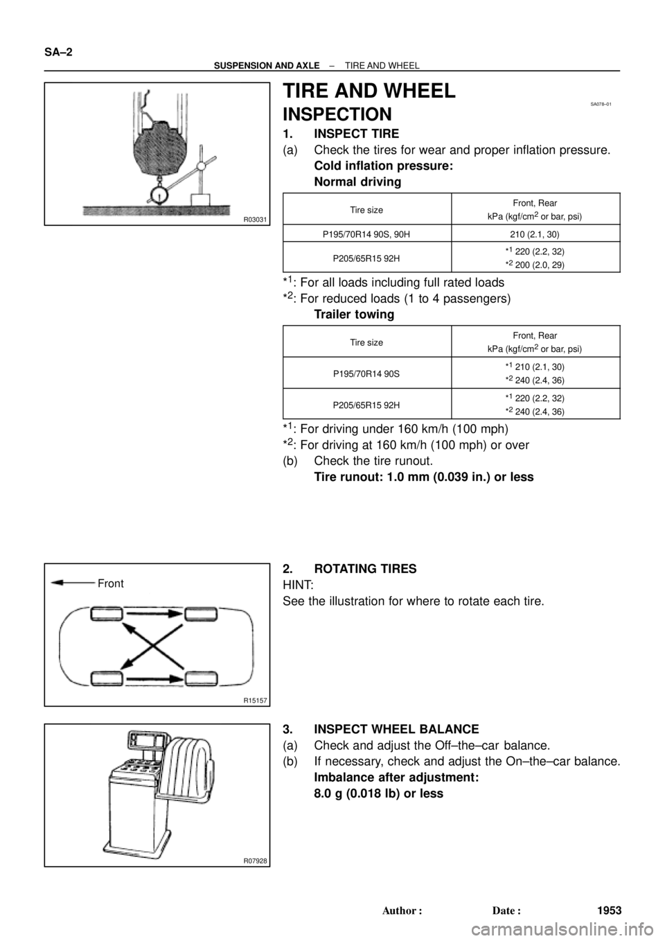
2. ROTATING TIRES
HINT:
See the illustration for where to rotate each tire.
3. INSPECT WHEEL BALANCE
(a) Check and adjust the Off±the±car balance.
(b) If necessary, check and adjust the On±the±car balance.
Imbalance after adjustment:
8.0 g (0.018 lb) or less
Page 3573 of 4592
SA08Q±01
FA1535
SST
W03093
W03142
± SUSPENSION AND AXLEFRONT DRIVE SHAFT (5S±FE)
SA±17
1968 Author�: Date�:
REMOVAL
NOTICE:
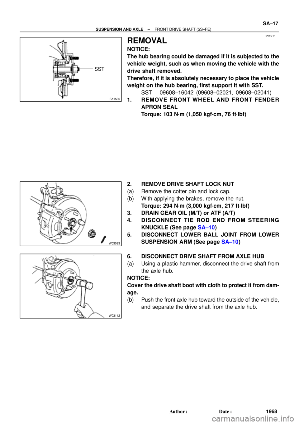
The hub bearing could be damaged if it is subjected to the
vehicle weight, such as when moving the vehicle with the
drive shaft removed.
Therefore, if it is absolutely necessary to place the vehicle
weight on the hub bearing, first support it with SST.
SST 09608±16042 (09608±02021, 09608±02041)
1. REMOVE FRONT WHEEL AND FRONT FENDER
APRON SEAL
Torque: 103 N´m (1,050 kgf´cm, 76 ft´lbf)
2. REMOVE DRIVE SHAFT LOCK NUT
(a) Remove the cotter pin and lock cap.
(b) With applying the brakes, remove the nut.
Torque: 294 N´m (3,000 kgf´cm, 217 ft´lbf)
3. DRAIN GEAR OIL (M/T) or ATF (A/T)
4. DISCONNECT TIE ROD END FROM STEERING
KNUCKLE (See page SA±10)
5. DISCONNECT LOWER BALL JOINT FROM LOWER
SUSPENSION ARM (See page SA±10)
6. DISCONNECT DRIVE SHAFT FROM AXLE HUB
(a) Using a plastic hammer, disconnect the drive shaft from
the axle hub.
NOTICE:
Cover the drive shaft boot with cloth to protect it from dam-
age.
(b) Push the front axle hub toward the outside of the vehicle,
and separate the drive shaft from the axle hub.
Page 3575 of 4592
SA08R±01
N00191
FA1615
Matchmarks
SA1443
Matchmarks
± SUSPENSION AND AXLEFRONT DRIVE SHAFT (5S±FE)
SA±19
1970 Author�: Date�:
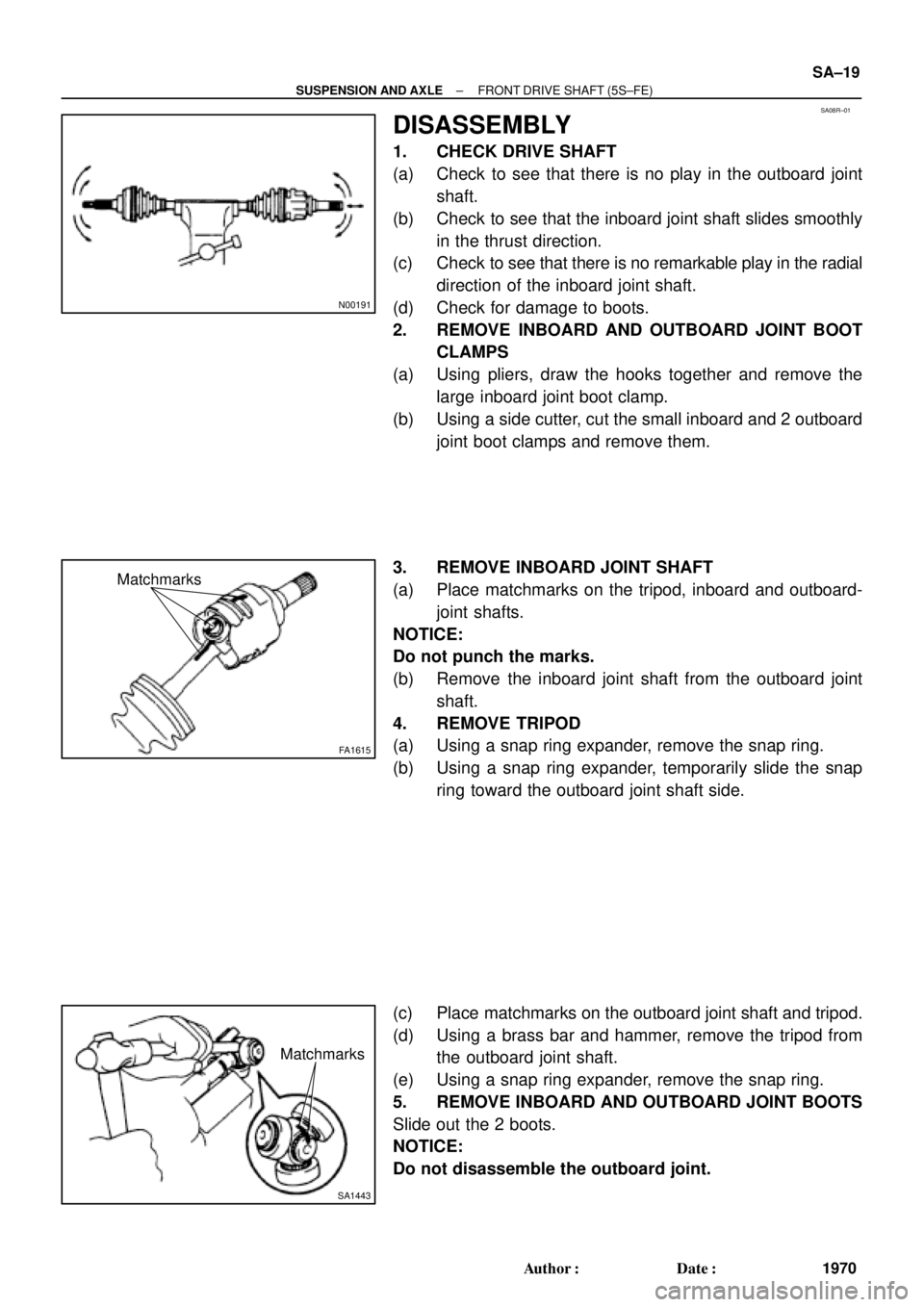
DISASSEMBLY
1. CHECK DRIVE SHAFT
(a) Check to see that there is no play in the outboard joint
shaft.
(b) Check to see that the inboard joint shaft slides smoothly
in the thrust direction.
(c) Check to see that there is no remarkable play in the radial
direction of the inboard joint shaft.
(d) Check for damage to boots.
2. REMOVE INBOARD AND OUTBOARD JOINT BOOT
CLAMPS
(a) Using pliers, draw the hooks together and remove the
large inboard joint boot clamp.
(b) Using a side cutter, cut the small inboard and 2 outboard
joint boot clamps and remove them.
3. REMOVE INBOARD JOINT SHAFT
(a) Place matchmarks on the tripod, inboard and outboard-
joint shafts.
NOTICE:
Do not punch the marks.
(b) Remove the inboard joint shaft from the outboard joint
shaft.
4. REMOVE TRIPOD
(a) Using a snap ring expander, remove the snap ring.
(b) Using a snap ring expander, temporarily slide the snap
ring toward the outboard joint shaft side.
(c) Place matchmarks on the outboard joint shaft and tripod.
(d) Using a brass bar and hammer, remove the tripod from
the outboard joint shaft.
(e) Using a snap ring expander, remove the snap ring.
5. REMOVE INBOARD AND OUTBOARD JOINT BOOTS
Slide out the 2 boots.
NOTICE:
Do not disassemble the outboard joint.
Page 3578 of 4592
F01747
Inboard Joint BootOutboard Joint Boot
Vinyl tape
R00764
SA±22
± SUSPENSION AND AXLEFRONT DRIVE SHAFT (5S±FE)
1973 Author�: Date�:
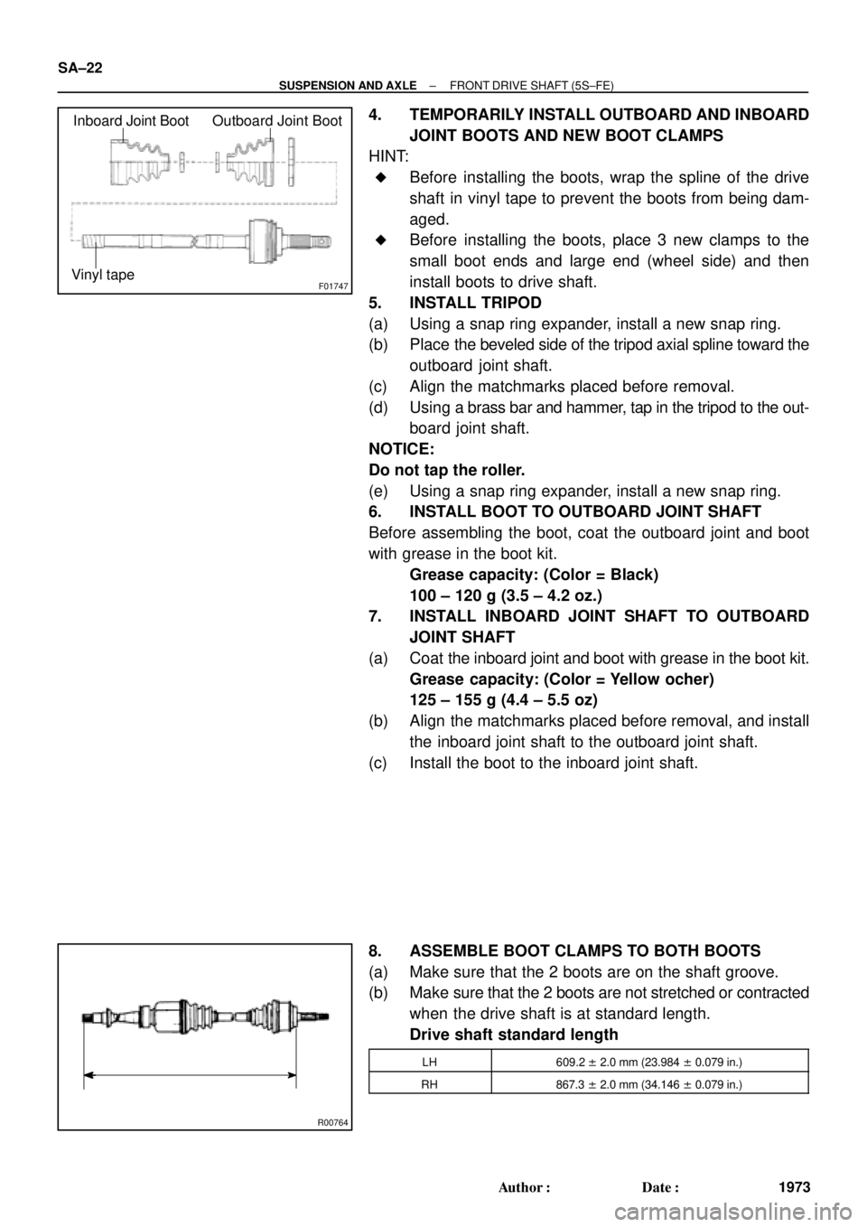
4. TEMPORARILY INSTALL OUTBOARD AND INBOARD
JOINT BOOTS AND NEW BOOT CLAMPS
HINT:
�Before installing the boots, wrap the spline of the drive
shaft in vinyl tape to prevent the boots from being dam-
aged.
�Before installing the boots, place 3 new clamps to the
small boot ends and large end (wheel side) and then
install boots to drive shaft.
5. INSTALL TRIPOD
(a) Using a snap ring expander, install a new snap ring.
(b) Place the beveled side of the tripod axial spline toward the
outboard joint shaft.
(c) Align the matchmarks placed before removal.
(d) Using a brass bar and hammer, tap in the tripod to the out-
board joint shaft.
NOTICE:
Do not tap the roller.
(e) Using a snap ring expander, install a new snap ring.
6. INSTALL BOOT TO OUTBOARD JOINT SHAFT
Before assembling the boot, coat the outboard joint and boot
with grease in the boot kit.
Grease capacity: (Color = Black)
100 ± 120 g (3.5 ± 4.2 oz.)
7. INSTALL INBOARD JOINT SHAFT TO OUTBOARD
JOINT SHAFT
(a) Coat the inboard joint and boot with grease in the boot kit.
Grease capacity: (Color = Yellow ocher)
125 ± 155 g (4.4 ± 5.5 oz)
(b) Align the matchmarks placed before removal, and install
the inboard joint shaft to the outboard joint shaft.
(c) Install the boot to the inboard joint shaft.
8. ASSEMBLE BOOT CLAMPS TO BOTH BOOTS
(a) Make sure that the 2 boots are on the shaft groove.
(b) Make sure that the 2 boots are not stretched or contracted
when the drive shaft is at standard length.
Drive shaft standard length
LH609.2 ± 2.0 mm (23.984 ± 0.079 in.)
RH867.3 ± 2.0 mm (34.146 ± 0.079 in.)
Page 3635 of 4592
W03142
R00647
LH:
W03144
RH:
± SUSPENSION AND AXLEFRONT DRIVE SHAFT
SA±7
6. DISCONNECT DRIVE SHAFT FROM AXLE HUB
(a) Using a plastic hammer, disconnect the drive shaft from
the axle hub.
NOTICE:
Be careful not to damage the boot and ABS speed sensor
rotor.
(b) Push the front axle hub toward the outside of the vehicle,
and separate the drive shaft from the axle hub.
7. REMOVE LH DRIVE SHAFT
(a) Using a hub nut wrench and wooden block or an equiva-
lent, remove the drive shaft.
(b) Using a screwdriver, remove the snap ring from the in-
board joint shaft.
NOTICE:
Be careful not to damage the boot and ABS speed sensor
rotor.
8. REMOVE RH DRIVE SHAFT
(a) Remove the bearing lock bolt.
(b) Using pliers, remove the snap ring and drive shaft.
NOTICE:
Be careful not to damage the boot and ABS speed sensor
rotor.