Page 3558 of 4592
R03031
SA078±01
R15157
Front
R07928
SA±2
± SUSPENSION AND AXLETIRE AND WHEEL
1953 Author�: Date�:
TIRE AND WHEEL
INSPECTION
1. INSPECT TIRE
(a) Check the tires for wear and proper inflation pressure.
Cold inflation pressure:
Normal driving
Tire sizeFront, Rear
kPa (kgf/cm2 or bar, psi)
P195/70R14 90S, 90H210 (2.1, 30)
P205/65R15 92H*1 220 (2.2, 32)
*2 200 (2.0, 29)
*1: For all loads including full rated loads
*
2: For reduced loads (1 to 4 passengers)
Trailer towing
Tire sizeFront, Rear
kPa (kgf/cm2 or bar, psi)
P195/70R14 90S*1 210 (2.1, 30)
*2 240 (2.4, 36)
P205/65R15 92H*1 220 (2.2, 32)
*2 240 (2.4, 36)
*1: For driving under 160 km/h (100 mph)
*
2: For driving at 160 km/h (100 mph) or over
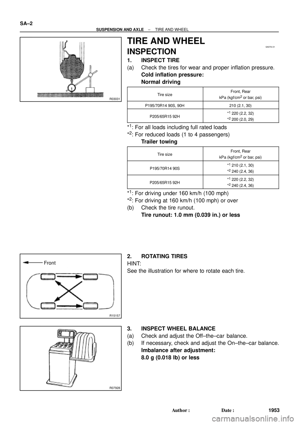
(b) Check the tire runout.
Tire runout: 1.0 mm (0.039 in.) or less
2. ROTATING TIRES
HINT:
See the illustration for where to rotate each tire.
3. INSPECT WHEEL BALANCE
(a) Check and adjust the Off±the±car balance.
(b) If necessary, check and adjust the On±the±car balance.
Imbalance after adjustment:
8.0 g (0.018 lb) or less
Page 3575 of 4592
SA08R±01
N00191
FA1615
Matchmarks
SA1443
Matchmarks
± SUSPENSION AND AXLEFRONT DRIVE SHAFT (5S±FE)
SA±19
1970 Author�: Date�:
DISASSEMBLY
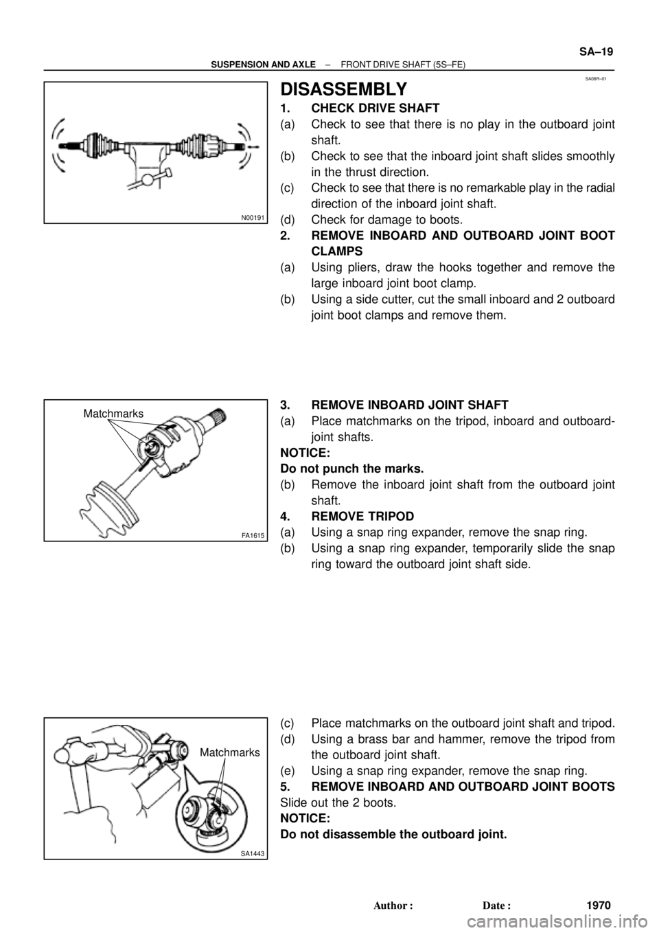
1. CHECK DRIVE SHAFT
(a) Check to see that there is no play in the outboard joint
shaft.
(b) Check to see that the inboard joint shaft slides smoothly
in the thrust direction.
(c) Check to see that there is no remarkable play in the radial
direction of the inboard joint shaft.
(d) Check for damage to boots.
2. REMOVE INBOARD AND OUTBOARD JOINT BOOT
CLAMPS
(a) Using pliers, draw the hooks together and remove the
large inboard joint boot clamp.
(b) Using a side cutter, cut the small inboard and 2 outboard
joint boot clamps and remove them.
3. REMOVE INBOARD JOINT SHAFT
(a) Place matchmarks on the tripod, inboard and outboard-
joint shafts.
NOTICE:
Do not punch the marks.
(b) Remove the inboard joint shaft from the outboard joint
shaft.
4. REMOVE TRIPOD
(a) Using a snap ring expander, remove the snap ring.
(b) Using a snap ring expander, temporarily slide the snap
ring toward the outboard joint shaft side.
(c) Place matchmarks on the outboard joint shaft and tripod.
(d) Using a brass bar and hammer, remove the tripod from
the outboard joint shaft.
(e) Using a snap ring expander, remove the snap ring.
5. REMOVE INBOARD AND OUTBOARD JOINT BOOTS
Slide out the 2 boots.
NOTICE:
Do not disassemble the outboard joint.
Page 3578 of 4592
F01747
Inboard Joint BootOutboard Joint Boot
Vinyl tape
R00764
SA±22
± SUSPENSION AND AXLEFRONT DRIVE SHAFT (5S±FE)
1973 Author�: Date�:
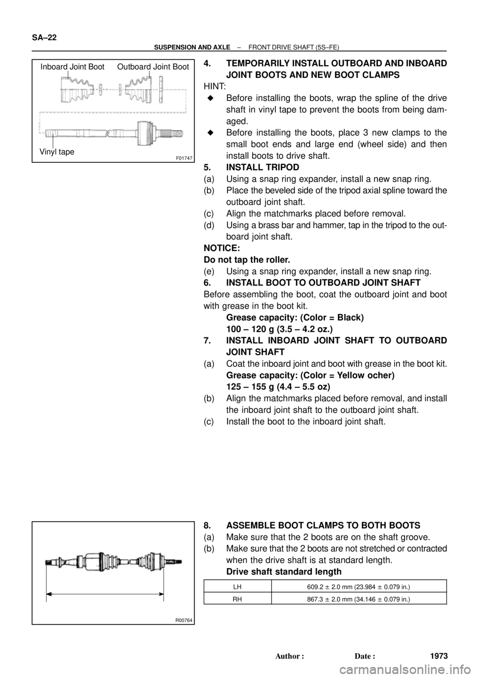
4. TEMPORARILY INSTALL OUTBOARD AND INBOARD
JOINT BOOTS AND NEW BOOT CLAMPS
HINT:
�Before installing the boots, wrap the spline of the drive
shaft in vinyl tape to prevent the boots from being dam-
aged.
�Before installing the boots, place 3 new clamps to the
small boot ends and large end (wheel side) and then
install boots to drive shaft.
5. INSTALL TRIPOD
(a) Using a snap ring expander, install a new snap ring.
(b) Place the beveled side of the tripod axial spline toward the
outboard joint shaft.
(c) Align the matchmarks placed before removal.
(d) Using a brass bar and hammer, tap in the tripod to the out-
board joint shaft.
NOTICE:
Do not tap the roller.
(e) Using a snap ring expander, install a new snap ring.
6. INSTALL BOOT TO OUTBOARD JOINT SHAFT
Before assembling the boot, coat the outboard joint and boot
with grease in the boot kit.
Grease capacity: (Color = Black)
100 ± 120 g (3.5 ± 4.2 oz.)
7. INSTALL INBOARD JOINT SHAFT TO OUTBOARD
JOINT SHAFT
(a) Coat the inboard joint and boot with grease in the boot kit.
Grease capacity: (Color = Yellow ocher)
125 ± 155 g (4.4 ± 5.5 oz)
(b) Align the matchmarks placed before removal, and install
the inboard joint shaft to the outboard joint shaft.
(c) Install the boot to the inboard joint shaft.
8. ASSEMBLE BOOT CLAMPS TO BOTH BOOTS
(a) Make sure that the 2 boots are on the shaft groove.
(b) Make sure that the 2 boots are not stretched or contracted
when the drive shaft is at standard length.
Drive shaft standard length
LH609.2 ± 2.0 mm (23.984 ± 0.079 in.)
RH867.3 ± 2.0 mm (34.146 ± 0.079 in.)
Page 3636 of 4592
SA1EA±02
N00191
F06526
BA
FA1615
Matchmarks
SA1443
Matchmarks
SA±8
± SUSPENSION AND AXLEFRONT DRIVE SHAFT
DISASSEMBLY
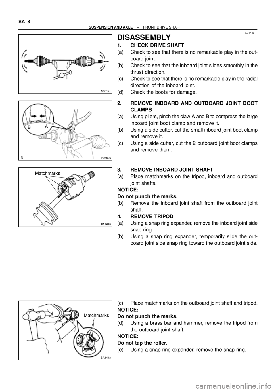
1. CHECK DRIVE SHAFT
(a) Check to see that there is no remarkable play in the out-
board joint.
(b) Check to see that the inboard joint slides smoothly in the
thrust direction.
(c) Check to see that there is no remarkable play in the radial
direction of the inboard joint.
(d) Check the boots for damage.
2. REMOVE INBOARD AND OUTBOARD JOINT BOOT
CLAMPS
(a) Using pliers, pinch the claw A and B to compress the large
inboard joint boot clamp and remove it.
(b) Using a side cutter, cut the small inboard joint boot clamp
and remove it.
(c) Using a side cutter, cut the 2 outboard joint boot clamps
and remove them.
3. REMOVE INBOARD JOINT SHAFT
(a) Place matchmarks on the tripod, inboard and outboard
joint shafts.
NOTICE:
Do not punch the marks.
(b) Remove the inboard joint shaft from the outboard joint
shaft.
4. REMOVE TRIPOD
(a) Using a snap ring expander, remove the inboard joint side
snap ring.
(b) Using a snap ring expander, temporarily slide the out-
board joint side snap ring toward the outboard joint side.
(c) Place matchmarks on the outboard joint shaft and tripod.
NOTICE:
Do not punch the marks.
(d) Using a brass bar and hammer, remove the tripod from
the outboard joint shaft.
NOTICE:
Do not tap the roller.
(e) Using a snap ring expander, remove the snap ring.
Page 3640 of 4592
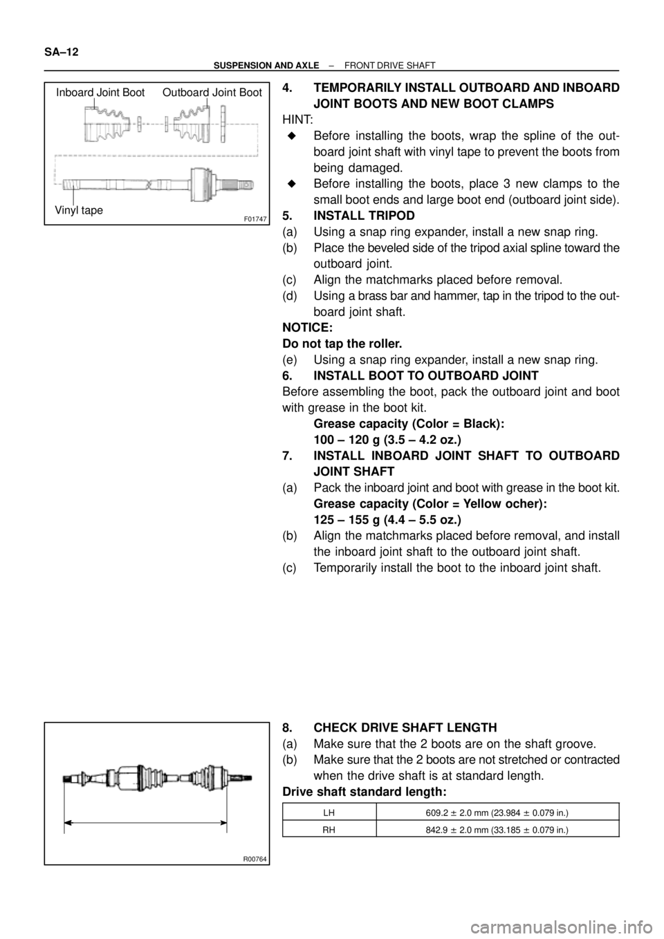
F01747
Inboard Joint BootOutboard Joint Boot
Vinyl tape
R00764
SA±12
± SUSPENSION AND AXLEFRONT DRIVE SHAFT
4. TEMPORARILY INSTALL OUTBOARD AND INBOARD
JOINT BOOTS AND NEW BOOT CLAMPS
HINT:
�Before installing the boots, wrap the spline of the out-
board joint shaft with vinyl tape to prevent the boots from
being damaged.
�Before installing the boots, place 3 new clamps to the
small boot ends and large boot end (outboard joint side).
5. INSTALL TRIPOD
(a) Using a snap ring expander, install a new snap ring.
(b) Place the beveled side of the tripod axial spline toward the
outboard joint.
(c) Align the matchmarks placed before removal.
(d) Using a brass bar and hammer, tap in the tripod to the out-
board joint shaft.
NOTICE:
Do not tap the roller.
(e) Using a snap ring expander, install a new snap ring.
6. INSTALL BOOT TO OUTBOARD JOINT
Before assembling the boot, pack the outboard joint and boot
with grease in the boot kit.
Grease capacity (Color = Black):
100 ± 120 g (3.5 ± 4.2 oz.)
7. INSTALL INBOARD JOINT SHAFT TO OUTBOARD
JOINT SHAFT
(a) Pack the inboard joint and boot with grease in the boot kit.
Grease capacity (Color = Yellow ocher):
125 ± 155 g (4.4 ± 5.5 oz.)
(b) Align the matchmarks placed before removal, and install
the inboard joint shaft to the outboard joint shaft.
(c) Temporarily install the boot to the inboard joint shaft.
8. CHECK DRIVE SHAFT LENGTH
(a) Make sure that the 2 boots are on the shaft groove.
(b) Make sure that the 2 boots are not stretched or contracted
when the drive shaft is at standard length.
Drive shaft standard length:
LH609.2 ± 2.0 mm (23.984 ± 0.079 in.)
RH842.9 ± 2.0 mm (33.185 ± 0.079 in.)