BR0AP±03
F07213
R02874
BR±22
± BRAKEFRONT BRAKE PAD
2045 Author�: Date�:
REPLACEMENT
1. REMOVE FRONT WHEEL
Remove the wheel and temporarily fasten the disc with hub
nuts.
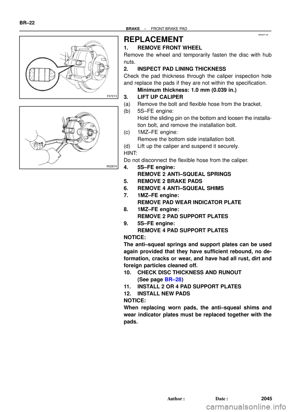
2. INSPECT PAD LINING THICKNESS
Check the pad thickness through the caliper inspection hole
and replace the pads if they are not within the specification.
Minimum thickness: 1.0 mm (0.039 in.)
3. LIFT UP CALIPER
(a) Remove the bolt and flexible hose from the bracket.
(b) 5S±FE engine:
Hold the sliding pin on the bottom and loosen the installa-
tion bolt, and remove the installation bolt.
(c) 1MZ±FE engine:
Remove the bottom side installation bolt.
(d) Lift up the caliper and suspend it securely.
HINT:
Do not disconnect the flexible hose from the caliper.
4. 5S±FE engine:
REMOVE 2 ANTI±SQUEAL SPRINGS
5. REMOVE 2 BRAKE PADS
6. REMOVE 4 ANTI±SQUEAL SHIMS
7. 1MZ±FE engine:
REMOVE PAD WEAR INDICATOR PLATE
8. 1MZ±FE engine:
REMOVE 2 PAD SUPPORT PLATES
9. 5S±FE engine:
REMOVE 4 PAD SUPPORT PLATES
NOTICE:
The anti±squeal springs and support plates can be used
again provided that they have sufficient rebound, no de-
formation, cracks or wear, and have had all rust, dirt and
foreign particles cleaned off.
10. CHECK DISC THICKNESS AND RUNOUT
(See page BR±28)
11. INSTALL 2 OR 4 PAD SUPPORT PLATES
12. INSTALL NEW PADS
NOTICE:
When replacing worn pads, the anti±squeal shims and
wear indicator plates must be replaced together with the
pads.
BR0B1±03
R00591
R00514
R10387
± BRAKEREAR BRAKE PAD
BR±37
2060 Author�: Date�:
REPLACEMENT
1. REMOVE REAR WHEEL
Remove the wheel and temporarily fasten the disc with the hub
nuts.
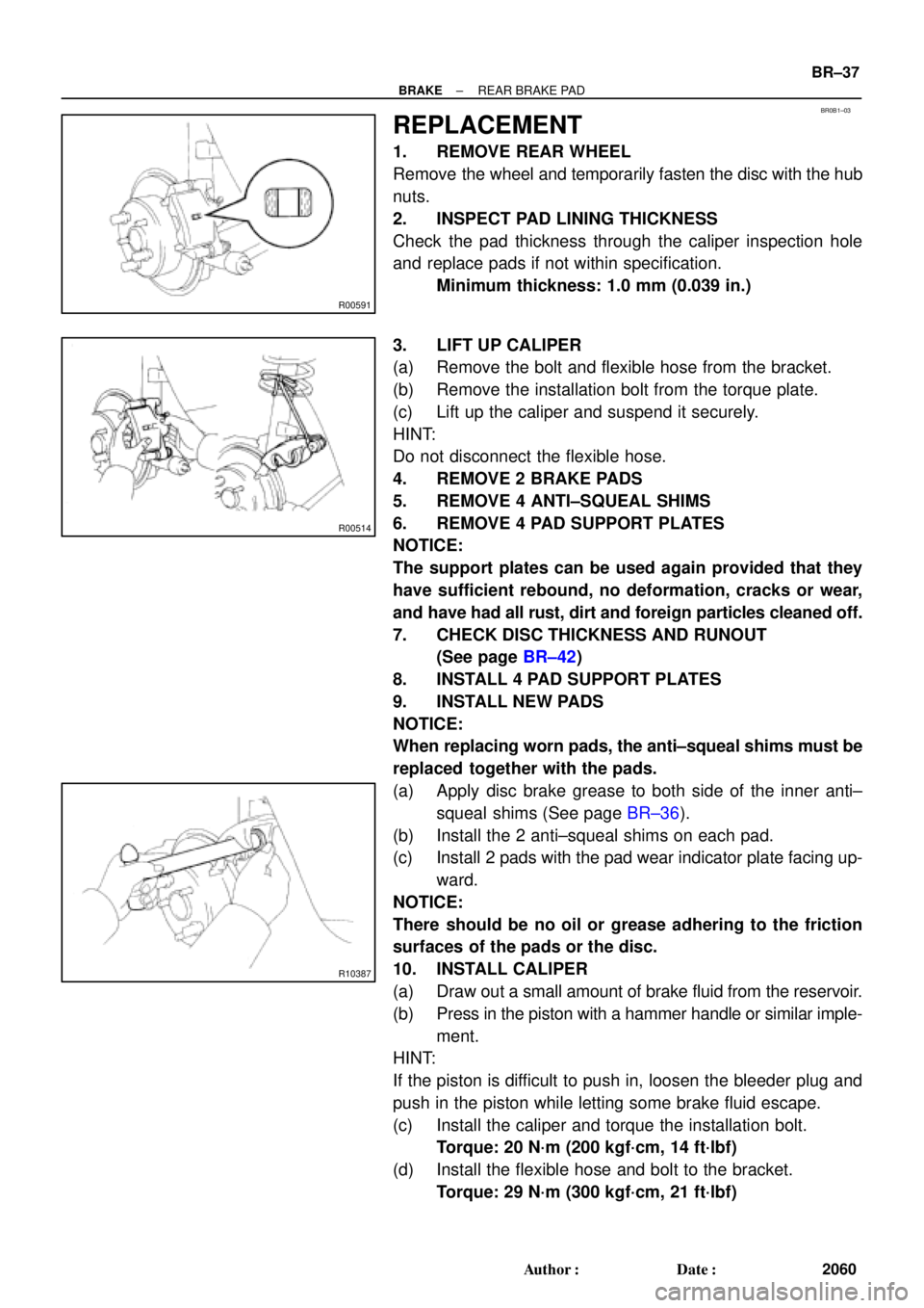
2. INSPECT PAD LINING THICKNESS
Check the pad thickness through the caliper inspection hole
and replace pads if not within specification.
Minimum thickness: 1.0 mm (0.039 in.)
3. LIFT UP CALIPER
(a) Remove the bolt and flexible hose from the bracket.
(b) Remove the installation bolt from the torque plate.
(c) Lift up the caliper and suspend it securely.
HINT:
Do not disconnect the flexible hose.
4. REMOVE 2 BRAKE PADS
5. REMOVE 4 ANTI±SQUEAL SHIMS
6. REMOVE 4 PAD SUPPORT PLATES
NOTICE:
The support plates can be used again provided that they
have sufficient rebound, no deformation, cracks or wear,
and have had all rust, dirt and foreign particles cleaned off.
7. CHECK DISC THICKNESS AND RUNOUT
(See page BR±42)
8. INSTALL 4 PAD SUPPORT PLATES
9. INSTALL NEW PADS
NOTICE:
When replacing worn pads, the anti±squeal shims must be
replaced together with the pads.
(a) Apply disc brake grease to both side of the inner anti±
squeal shims (See page BR±36).
(b) Install the 2 anti±squeal shims on each pad.
(c) Install 2 pads with the pad wear indicator plate facing up-
ward.
NOTICE:
There should be no oil or grease adhering to the friction
surfaces of the pads or the disc.
10. INSTALL CALIPER
(a) Draw out a small amount of brake fluid from the reservoir.
(b) Press in the piston with a hammer handle or similar imple-
ment.
HINT:
If the piston is difficult to push in, loosen the bleeder plug and
push in the piston while letting some brake fluid escape.
(c) Install the caliper and torque the installation bolt.
Torque: 20 N´m (200 kgf´cm, 14 ft´lbf)
(d) Install the flexible hose and bolt to the bracket.
Torque: 29 N´m (300 kgf´cm, 21 ft´lbf)