Page 48 of 4592

(B)
± AIR CONDITIONINGCOMPRESSOR AND MAGNETIC CLUTCH
AC±47
2529 Author�: Date�:
INSTALLATION
1. 5S±FE engine models:
INSTALL COMPRESSOR
(a) Install the compressor with 3 bolts.")
AC0M9±02
N20259
(A)
(B)
± AIR CONDITIONINGCOMPRESSOR AND MAGNETIC CLUTCH
AC±47
2529 Author�: Date�:
INSTALLATION
1. 5S±FE engine models:
INSTALL COMPRESSOR
(a) Install the compressor with 3 bolts.
Torque: 25 N´m (250 kgf´cm, 18 ft´lbf)
(b) Connect the connector.
2. 1MZ±FE engine models:
INSTALL COMPRESSOR
(a) Install the compressor with 3 bolts.
Torque: 25 N´m (250 kgf´cm, 18 ft´lbf)
(b) Install the drive belt adjusting bar bracket with 2 bolts and
nut.
Torque:
Bolt (A): 25 N´m (250 kgf´cm, 18 ft´lbf)
Bolt (B): 18 N´m (185 kgf´cm, 13 ft´lbf)
Nut: 25 N´m (250 kgf´cm, 18 ft´lbf)
(c) Connect the connector.
3. 5S±FE engine models:
CONNECT DISCHARGE AND SUCTION HOSE
Connect the both hoses with the 2 bolts.
Torque: 10 N´m (100 kgf´cm, 7 ft´lbf)
NOTICE:
Hoses should be connected immediately after the caps
have been removed.
HINT:
Lubricate 2 new O±rings with compressor oil and install the
tubes.
4. 1MZ±FE engine models:
INSTALL GENERATOR
(a) Mount generator on the generator bracket with the pivot
bolt and adjusting lock bolt. Do not tighten the bolts yet.
(b) Connect the generator connector.
(c) Connect the generator wire with the nut.
Page 49 of 4592

AC±48
± AIR CONDITIONINGCOMPRESSOR AND MAGNETIC CLUTCH
2530 Author�: Date�:
5. 1MZ±FE engine models:
CONNECT DISCHARGE HOSE
Connect the discharge hose with the bolt.
Torque: 10 N´m (100 kgf´cm, 7 ft´lbf)
NOTICE:
Hoses should be connected immediately after the caps
have been removed.
HINT:
Lubricate a new O±ring with compressor oil and install the tube.
6. INSTALL SUCTION HOSE
(a) Install the suction hose and tighten the bolt and nut.
Torque:
Piping joint: 32 N´m (330 kgf´cm, 24 ft´lbf)
Block joint: 10 N´m (100 kgf´cm, 7 ft´lbf)
HINT:
Lubricate 2 new O±rings with compressor oil and install the
hose.
(b) Install the suction hose clamping bolt.
(c) Connect the wire harness clamp.
7. INSTALL AND CHECK DRIVE BELT
(See page AC±18, AC±16)
8. CONNECT NEGATIVE (±) TERMINAL CABLE TO BAT-
TERY
9. EVACUATE AIR FROM REFRIGERATION SYSTEM
AND CHARGE SYSTEM WITH REFRIGERANT
Specified amount: 800 ± 50 g (28.22 ± 1.76 oz.)
10. INSPECT FOR LEAKAGE OF REFRIGERANT
Using a gas leak detector, check for leakage of refrigerant.
If there is leakage, check the tightening torque at the joints.
11. INSPECT A/C OPERATION
Page 50 of 4592
AC0MA±01
± AIR CONDITIONINGRECEIVER
AC±49
2531 Author�: Date�:
RECEIVER
ON±VEHICLE INSPECTION
INSPECT FITTINGS FOR LEAKAGE
Using a gas leak detector, check for leakage.
If there is leakage, check the tightening torque at the joints.
Page 51 of 4592

AC0MB±02
N20279
AC±50
± AIR CONDITIONINGRECEIVER
2532 Author�: Date�:
REMOVAL
1. DISCHARGE REFRIGERANT FROM REFRIGERATION
SYSTEM
HINT:
At the time of installation, please refer to the following item.
Evacuate air from refrigeration system.
Charge system with refrigerant and inspect for leakage of refrig-
erant.
Specified amount: 800 ± 50 g (28.22 ± 1.76 oz.)
2. REMOVE RADIATOR UPPER SUPPORT SEAL
3. DISCONNECT 2 LIQUID TUBES FROM RECEIVER
Remove the 2 bolts and both tubes.
Torque: 5.4 N´m (55 kgf´cm, 48 in.´lbf)
NOTICE:
Cap the open fittings immediately to keep moisture or dirt
out of the system.
HINT:
At the time of installation, please refer to the following item.
Lubricate 2 new O±rings with compressor oil and install the
tubes.
4. REMOVE RECEIVER
(a) Remove the holder bolt and pull out receiver downward.
HINT:
At the time of installation, please refer to the following item.
If receiver was replaced, add compressor oil to compressor.
Add 20 cc (0.71 fl.oz.)
Compressor oil: ND±OIL 8 or equivalent
(b) Remove the 2 bolts and holder.
Page 53 of 4592
AC0MD±01
AC±52
± AIR CONDITIONINGCONDENSER
2534 Author�: Date�:
CONDENSER
ON±VEHICLE INSPECTION
1. INSPECT CONDENSER FINS FOR BLOCKAGE OR DAMAGE
�If the fins are clogged, wash them with water and dry with compressed air.
NOTICE:
Be careful not to damage the fins.
�If the fins are bent, straighten them with a screwdriver or pliers.
2. INSPECT CONDENSER AND FITTINGS FOR LEAKAGE
Using a gas leak detector, check for leakage of refrigerant.
If there is leakage, check the tightening torque at the joints.
Page 54 of 4592

AC0ME±02
I03836
± AIR CONDITIONINGCONDENSER
AC±53
2535 Author�: Date�:
REMOVAL
1. DISCHARGE REFRIGERANT FROM REFRIGERATION
SYSTEM
HINT:
At the time of installation, please refer to the following item.
Evacuate air from refrigeration system.
Charge system with refrigerant and inspect for leakage of refrig-
erant.
Specified amount: 800 ± 50 g (28.22 ± 1.76 oz.)
2. REMOVE UPPER RADIATOR SUPPORTS
3. REMOVE RECEIVER AND HOLDER
(See page AC±50)
4. DISCONNECT DISCHARGE HOSE
Loosen the nut and disconnect the discharge hose.
Torque: 10 N´m (100 kgf´cm, 7 ft´lbf)
NOTICE:
Cap the open fittings immediately to keep moisture or dirt
out of the system.
HINT:
At the time of installation, please refer to the following item.
Lubricate a new O±ring with compressor oil and install the tube.
5. REMOVE LIQUID TUBE
Loosen the nut and remove the liquid tube.
Torque: 14 N´m (140 kgf´cm, 10 ft´lbf)
NOTICE:
Cap the open fittings immediately to keep moisture or dirt
out of the system.
HINT:
At the time of installation, please refer to the following item.
Lubricate a new O±ring with compressor oil and install the tube.
Page 63 of 4592
N20246
AC±62
± AIR CONDITIONINGEXPANSION VALVE
2544 Author�: Date�:
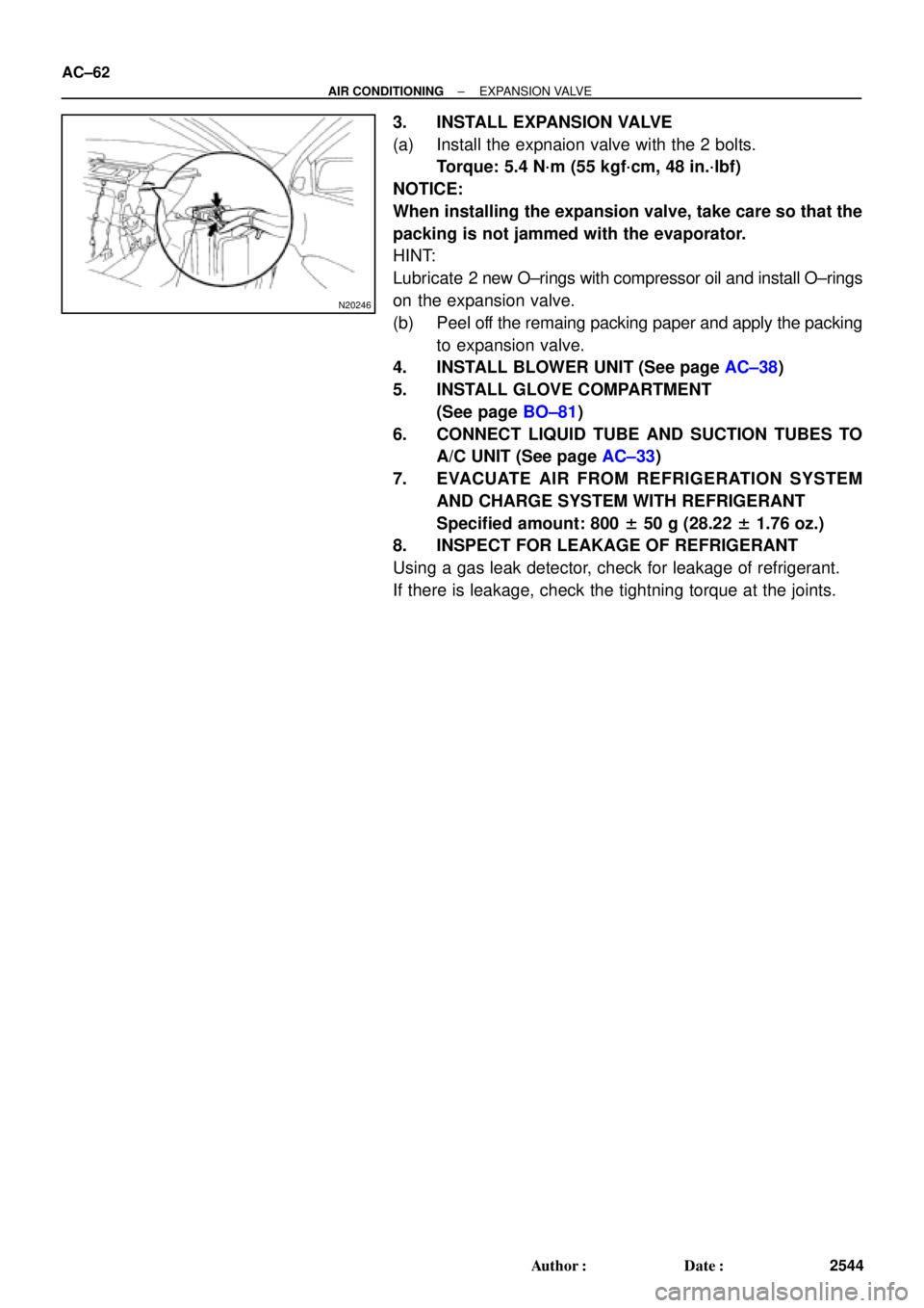
3. INSTALL EXPANSION VALVE
(a) Install the expnaion valve with the 2 bolts.
Torque: 5.4 N´m (55 kgf´cm, 48 in.´lbf)
NOTICE:
When installing the expansion valve, take care so that the
packing is not jammed with the evaporator.
HINT:
Lubricate 2 new O±rings with compressor oil and install O±rings
on the expansion valve.
(b) Peel off the remaing packing paper and apply the packing
to expansion valve.
4. INSTALL BLOWER UNIT (See page AC±38)
5. INSTALL GLOVE COMPARTMENT
(See page BO±81)
6. CONNECT LIQUID TUBE AND SUCTION TUBES TO
A/C UNIT (See page AC±33)
7. EVACUATE AIR FROM REFRIGERATION SYSTEM
AND CHARGE SYSTEM WITH REFRIGERANT
Specified amount: 800 ± 50 g (28.22 ± 1.76 oz.)
8. INSPECT FOR LEAKAGE OF REFRIGERANT
Using a gas leak detector, check for leakage of refrigerant.
If there is leakage, check the tightning torque at the joints.
Page 69 of 4592
AC0N3±02
N20292
AC±68
± AIR CONDITIONINGPRESSURE SWITCH
2550 Author�: Date�:
REMOVAL
1. DISCHARGE REFRIGERANT FROM REFRIGERATION
SYSTEM
HINT:
At the time of installation, please refer to the following item.
Evacuate air from refrigeration system.
Charge system with refrigerant and inspect for leakage of refrig-
erant.
Specified amount: 800 ± 50 g (28.22 ± 1.76 oz.)
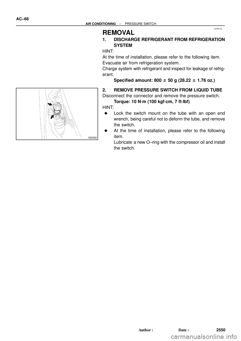
2. REMOVE PRESSURE SWITCH FROM LIQUID TUBE
Disconnect the connector and remove the pressure switch.
Torque: 10 N´m (100 kgf´cm, 7 ft´lbf)
HINT:
�Lock the switch mount on the tube with an open end
wrench, being careful not to deform the tube, and remove
the switch.
�At the time of installation, please refer to the following
item.
Lubricate a new O±ring with the compressor oil and install
the switch.