Page 115 of 4592
AUTOMATIC TRANSAXLE UNIT
AX±21
1914 Author�: Date�:
25. REMOVE EXHAUST FRONT PIPE
(a) Remove the 2 nuts and exhaust front pipe clamp.
Torque:")
Q10060
Q00068
Q08532
Q10061
± AUTOMATIC TRANSAXLE (A140E)AUTOMATIC TRANSAXLE UNIT
AX±21
1914 Author�: Date�:
25. REMOVE EXHAUST FRONT PIPE
(a) Remove the 2 nuts and exhaust front pipe clamp.
Torque: 33 N´m (330 kgf´cm, 24 ft´lbf)
(b) Remove the 2 bolts and exhaust pipe No.1 support brack-
et.
Torque: 33 N´m (330 kgf´cm, 24 ft´lbf)
(c) Remove the 3 nuts.
Torque: 62 N´m (630 kgf´cm, 46 ft´lbf)
HINT:
At the time of installation, please refer to the following item.
Replace the used nuts with new ones.
(d) Remove the 2 bolts, nuts and front exhaust pipe.
Torque: 56 N´m (570 kgf´cm, 41 ft´lbf)
HINT:
At the time of installation, please refer to the following item.
Replace the used nuts with new ones.
(e) Remove the 2 gaskets.
HINT:
At the time of installation, please refer to the following item.
Replace the used gaskets with new ones.
26. REMOVE FRONT SIDE ENGINE MOUNTING INSULA-
TOR BOLT
Torque:
TMC made: 80 N´m (820 kgf´cm, 59 ft´lbf)
TMMK made:
Green color bolt: 66 N´m (670 kgf´cm, 48 ft´lbf)
Silver color bolt: 44 N´m (450 kgf´cm, 32 ft´lbf)
27. REMOVE REAR SIDE ENGINE MOUNTING NUT
(a) Remove the 2 grommets.
(b) Remove the 3 nuts.
Torque: 66 N´m (670 kgf´cm, 48 ft´lbf)
28. REMOVE LEFT SIDE TRANSAXLE MOUNTING NUT
(a) Remove the 2 grommets.
(b) Remove the 2 nuts.
Torque: 80 N´m (820 kgf´cm, 59 ft´lbf)
Page 116 of 4592
Q10062
Q10063
Q06479
Q10041
Q10037
AX±22
± AUTOMATIC TRANSAXLE (A140E)AUTOMATIC TRANSAXLE UNIT
1915 Author�: Date�:
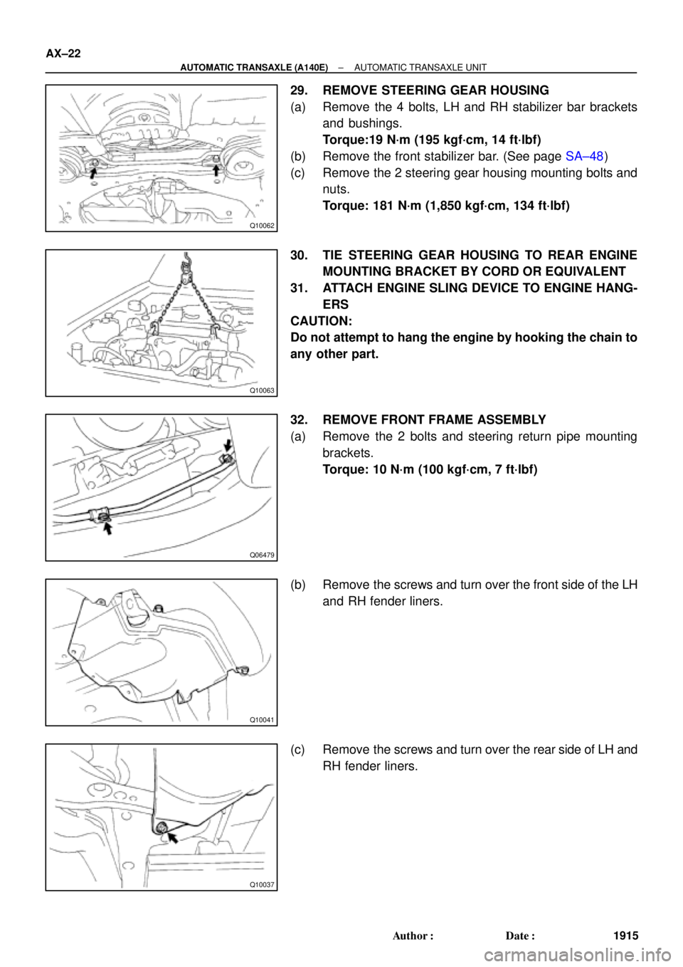
29. REMOVE STEERING GEAR HOUSING
(a) Remove the 4 bolts, LH and RH stabilizer bar brackets
and bushings.
Torque:19 N´m (195 kgf´cm, 14 ft´lbf)
(b) Remove the front stabilizer bar. (See page SA±48)
(c) Remove the 2 steering gear housing mounting bolts and
nuts.
Torque: 181 N´m (1,850 kgf´cm, 134 ft´lbf)
30. TIE STEERING GEAR HOUSING TO REAR ENGINE
MOUNTING BRACKET BY CORD OR EQUIVALENT
31. ATTACH ENGINE SLING DEVICE TO ENGINE HANG-
ERS
CAUTION:
Do not attempt to hang the engine by hooking the chain to
any other part.
32. REMOVE FRONT FRAME ASSEMBLY
(a) Remove the 2 bolts and steering return pipe mounting
brackets.
Torque: 10 N´m (100 kgf´cm, 7 ft´lbf)
(b) Remove the screws and turn over the front side of the LH
and RH fender liners.
(c) Remove the screws and turn over the rear side of LH and
RH fender liners.
Page 117 of 4592
Q10172
Front
Q10064
Rear
Q10065
TMC : Bolt
TMMK : Nut
± AUTOMATIC TRANSAXLE (A140E)AUTOMATIC TRANSAXLE UNIT
AX±23
1916 Author�: Date�:
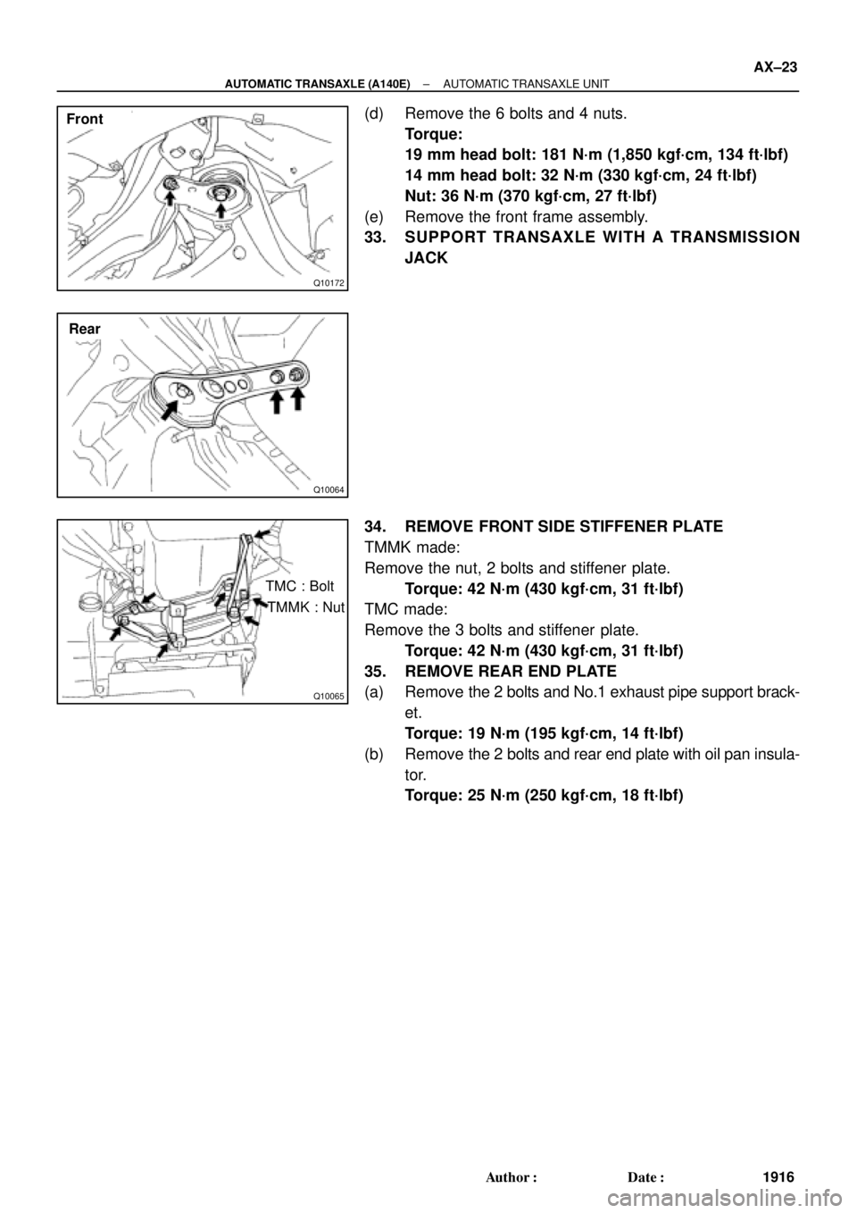
(d) Remove the 6 bolts and 4 nuts.
Torque:
19 mm head bolt: 181 N´m (1,850 kgf´cm, 134 ft´lbf)
14 mm head bolt: 32 N´m (330 kgf´cm, 24 ft´lbf)
Nut: 36 N´m (370 kgf´cm, 27 ft´lbf)
(e) Remove the front frame assembly.
33. SUPPORT TRANSAXLE WITH A TRANSMISSION
JACK
34. REMOVE FRONT SIDE STIFFENER PLATE
TMMK made:
Remove the nut, 2 bolts and stiffener plate.
Torque: 42 N´m (430 kgf´cm, 31 ft´lbf)
TMC made:
Remove the 3 bolts and stiffener plate.
Torque: 42 N´m (430 kgf´cm, 31 ft´lbf)
35. REMOVE REAR END PLATE
(a) Remove the 2 bolts and No.1 exhaust pipe support brack-
et.
Torque: 19 N´m (195 kgf´cm, 14 ft´lbf)
(b) Remove the 2 bolts and rear end plate with oil pan insula-
tor.
Torque: 25 N´m (250 kgf´cm, 18 ft´lbf)
Page 118 of 4592
Q10066
AX±24
± AUTOMATIC TRANSAXLE (A140E)AUTOMATIC TRANSAXLE UNIT
1917 Author�: Date�:
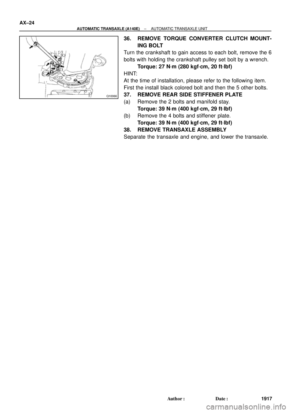
36. REMOVE TORQUE CONVERTER CLUTCH MOUNT-
ING BOLT
Turn the crankshaft to gain access to each bolt, remove the 6
bolts with holding the crankshaft pulley set bolt by a wrench.
Torque: 27 N´m (280 kgf´cm, 20 ft´lbf)
HINT:
At the time of installation, please refer to the following item.
First the install black colored bolt and then the 5 other bolts.
37. REMOVE REAR SIDE STIFFENER PLATE
(a) Remove the 2 bolts and manifold stay.
Torque: 39 N´m (400 kgf´cm, 29 ft´lbf)
(b) Remove the 4 bolts and stiffener plate.
Torque: 39 N´m (400 kgf´cm, 29 ft´lbf)
38. REMOVE TRANSAXLE ASSEMBLY
Separate the transaxle and engine, and lower the transaxle.
Page 119 of 4592
AX03I±01
AT3412
± AUTOMATIC TRANSAXLE (A140E)AUTOMATIC TRANSAXLE UNIT
AX±25
1918 Author�: Date�:
INSTALLATION
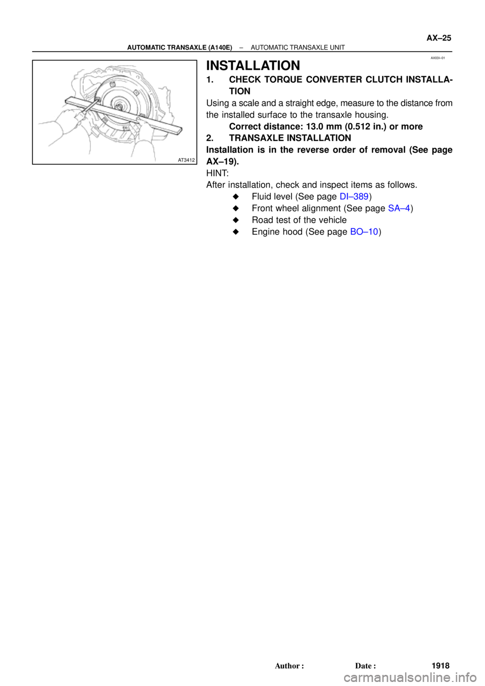
1. CHECK TORQUE CONVERTER CLUTCH INSTALLA-
TION
Using a scale and a straight edge, measure to the distance from
the installed surface to the transaxle housing.
Correct distance: 13.0 mm (0.512 in.) or more
2. TRANSAXLE INSTALLATION
Installation is in the reverse order of removal (See page
AX±19).
HINT:
After installation, check and inspect items as follows.
�Fluid level (See page DI±389)
�Front wheel alignment (See page SA±4)
�Road test of the vehicle
�Engine hood (See page BO±10)
Page 120 of 4592
TORQUE CONVERTER CLUTCH AND DRIVE PLATE
1919 Author�: Date�:
TORQUE CONVERTER CLUTCH
AND DRIVE PLATE
INSPECTI")
AT0953
SST
AX03J±01
AT3306
Hold
TurnLock
Free
Q04237
AX±26
± AUTOMATIC TRANSAXLE (A140E)TORQUE CONVERTER CLUTCH AND DRIVE PLATE
1919 Author�: Date�:
TORQUE CONVERTER CLUTCH
AND DRIVE PLATE
INSPECTION
1. INSPECT ONE±WAY CLUTCH
(a) Install SST into the inner race of the one±way clutch.
SST 09350±32014 (09351±32010)
(b) Install SST so that it fits in the notch of the converter hub
and outer race of the one±way clutch.
SST 09350±32014 (09351±32020)
(c) With the torque converter clutch standing on its side,the
clutch locks when turned counterclockwise, and rotates
freely and smoothly clockwise.
If necessary, clean the converter and retest the clutch. Replace
the converter clutch if the clutch still fails the test.
2. MEASURE DRIVE PLATE RUNOUT AND INSPECT
RING GEAR
Set up a dial indicator and measure the drive plate runout.
Maximum runout: 0.20 mm (0.0079 in.)
If the runout is not within the specification or if the ring gear is
damaged, replace the drive plate. If installing a new drive plate,
note the orientation of spacers and tighten the bolts.
Torque: 83 N´m (850 kgf´cm, 61 ft´lbf)
Page 121 of 4592
AT4184
± AUTOMATIC TRANSAXLE (A140E)TORQUE CONVERTER CLUTCH AND DRIVE PLATE
AX±27
1920 Author�: Date�:
3. MEASURE TORQUE CONVERTER CLUTCH SLEEVE
RUNOUT
(a) Temporarily mount the torque converter clutch to the drive
plate.
Set up a dial indicator and measure the torque converter
clutch sleeve runout.
Maximum runout: 0.30 mm (0.0118 in.)
If the runout is not within the specification, try to correct by reori-
enting the installation of the torque converter clutch. If exces-
sive runout cannot be corrected, replace the torque converter
clutch.
HINT:
Mark the position of the torque converter clutch to ensure the
correct installation.
(b) Remove the torque converter clutch.
Page 124 of 4592
Q05725
AX03N±01
Q04678
Clip O±Ring Driven GearVehicle Speed Sensor
± AUTOMATIC TRANSAXLE (A541E)VEHICLE SPEED SENSOR
AX±3
1923 Author�: Date�:
VEHICLE SPEED SENSOR
ON±VEHICLE REPAIR
1. REMOVE AIR CLEANER ASSEMBLY
2. DISCONNECT VEHICLE SPEED SENSOR CONNEC-
TOR
3. REMOVE VEHICLE SPEED SENSOR ASSEMBLY
(a) Remove the bolt and vehicle speed sensor assembly.
(b) Remove the clip and driven gear from the vehicle speed
sensor.
(c) Remove the O±ring from the vehicle speed sensor.
4. INSTALL VEHICLE SPEED SENSOR ASSEMBLY
(a) Coat a new O±ring with ATF and install it to the vehicle
speed sensor.
(b) Install the driven gear to the vehicle speed sensor and
clip.
(c) Install the vehicle speed sensor assembly with the bolt.
Torque: 4.9 N´m (50 kgf´cm, 43 in.´lbf)
5. CONNECT VEHICLE SPEED SENSOR CONNECTOR
6. INSTALL AIR CLEANER ASSEMBLY