Page 149 of 4592
AUTOMATIC TRANSAXLE UNIT
1948 Author�: Date�:
(d) Remove the 6 bolts and 4 nuts.
Torque:
19 mm head bo")
Q10172
Front
Q10064
Rear
Q04660
Q10036
Z14284
Left and lower AX±28
± AUTOMATIC TRANSAXLE (A541E)AUTOMATIC TRANSAXLE UNIT
1948 Author�: Date�:
(d) Remove the 6 bolts and 4 nuts.
Torque:
19 mm head bolt: 181 N´m (1,850 kgf´cm, 134 ft´lbf)
14 mm head bolt: 32 N´m (330 kgf´cm, 24 ft´lbf)
Nut: 36 N´m (370 kgf´cm, 27 ft´lbf)
(e) Remove the front frame assembly.
33. SUPPORT TRANSAXLE WITH A TRANSMISSION
JACK
34. REMOVE TORQUE CONVERTER CLUTCH MOUNT-
ING BOLTS
Turn the crankshaft to gain access to each bolt, remove the 6
bolts with holding the crankshaft pulley bolt by a wrench.
Torque: 41 N´m (420 kgf´cm, 30 ft´lbf)
HINT:
At the time of installation, please refer to the following item.
First install black colored bolt and then the 5 other bolts.
35. REMOVE EXHAUST MANIFOLD PLATE
(a) Remove the bolt, nut and exhaust manifold plate.
Torque:
Except California: 20 N´m (200 kgf´cm, 15 ft´lbf)
California: 34 N´m (350 kgf´cm, 25 ft´lbf)
36. REMOVE 3 LOWER TRANSAXLE±TO±ENGINE
BOLTS
Torque: 46 N´m (470 kgf´cm, 34 ft´lbf)
37. REMOVE TRANSAXLE ASSEMBLY
Separate the transaxle and engine, and lower the transaxle.
Page 150 of 4592
AX03Z±01
AT3412
± AUTOMATIC TRANSAXLE (A541E)AUTOMATIC TRANSAXLE UNIT
AX±29
1949 Author�: Date�:
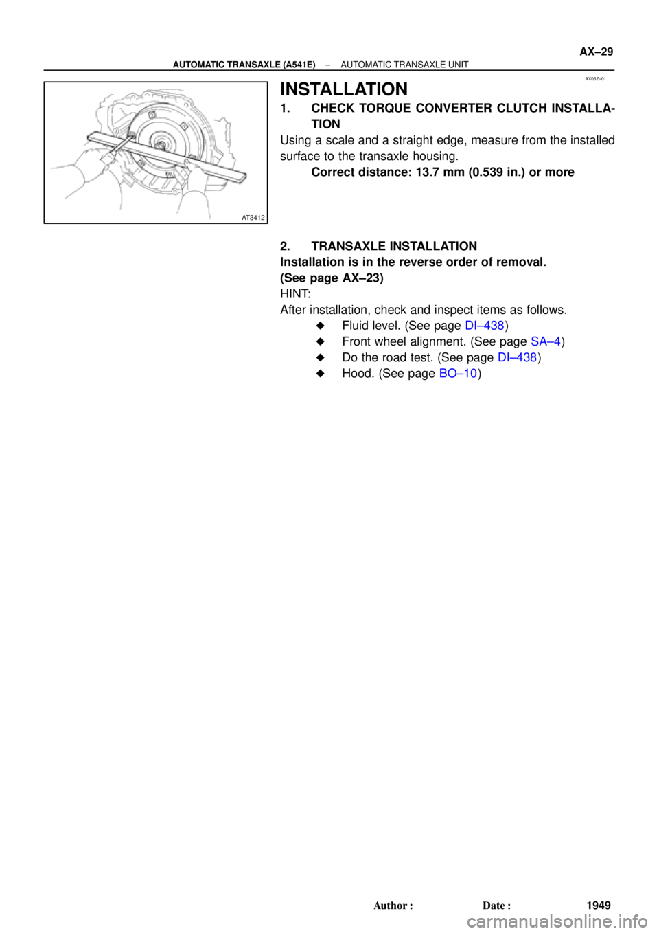
INSTALLATION
1. CHECK TORQUE CONVERTER CLUTCH INSTALLA-
TION
Using a scale and a straight edge, measure from the installed
surface to the transaxle housing.
Correct distance: 13.7 mm (0.539 in.) or more
2. TRANSAXLE INSTALLATION
Installation is in the reverse order of removal.
(See page AX±23)
HINT:
After installation, check and inspect items as follows.
�Fluid level. (See page DI±438)
�Front wheel alignment. (See page SA±4)
�Do the road test. (See page DI±438)
�Hood. (See page BO±10)
Page 151 of 4592
TORQUE CONVERTER CLUTCH AND DRIVE PLATE
1950 Author�: Date�:
TORQUE CONVERTER CLUTCH
AND DRIVE PL")
AX040±01
AT0952
SST
AT0953
SST
AT3306
Hold
Lock
Free
Turn
AT2821
AX±30
± AUTOMATIC TRANSAXLE (A541E)TORQUE CONVERTER CLUTCH AND DRIVE PLATE
1950 Author�: Date�:
TORQUE CONVERTER CLUTCH
AND DRIVE PLATE
INSPECTION
1. INSPECT ONE±WAY CLUTCH
(a) Install SST into the inner race of the one±way clutch.
SST 09350±32014 (09351±32020)
(b) Install SST so that it fits in the notch of the converter hub
and outer race of the one±way clutch.
SST 09350±32014 (09351±32010)
(c) With the torque converter clutch standing on its side,the
clutch locks when turned counterclockwise, and rotates
freely and smoothly clockwise.
If necessary, clean the converter and retest the clutch.
Replace the converter if the clutch still fails the test.
2. MEASURE DRIVE PLATE RUNOUT AND INSPECT
RING GEAR
(a) Set up a dial indicator, and measure the drive plate run-
out.
(b) Check the damage of the ring gear.
Maximum runout: 0.20 mm (0.0079 in.)
If the runout is not within specification or ring gear is damaged,
replace the drive plate.
Torque: 83 N´m (850 kgf´cm, 61 ft´lbf)
Page 152 of 4592
AT4184
± AUTOMATIC TRANSAXLE (A541E)TORQUE CONVERTER CLUTCH AND DRIVE PLATE
AX±31
1951 Author�: Date�:
3. MEASURE TORQUE CONVERTER CLUTCH SLEEVE
RUNOUT
(a) Temporarily mount the torque converter clutch to the drive
plate. Set up a dial indicator and measure the torque con-
verter clutch sleeve runout.
Maximum runout: 0.30 mm (0.0118 in.)
If the runout is not within the specification, try to correct by reori-
enting the installation of the converter.
HINT:
Mark the position of the converter to ensure the correct installa-
tion.
(b) Remove the torque converter clutch.
Page 155 of 4592
INTRODUCTIONHOW TO USE THIS MANUAL ±
IN±3
CAUTIONS, NOTICES, HINTS:
�CAUTIONS are presented in bold type, and indicate there is a possibility of injury to you or other
people.
�NOTICES are also presented in bold type, and indicate the possibility of damage to the compo-
nents being repaired.
�HINTS are separated from the text but do not appear in bold. They provide additional information
to help you perform the repair efficiently.
SI UNIT
The UNITS given in this manual are primarily expressed according to the SI UNIT (International System
of Unit), and alternately expressed in the metric system and in the English system.
Example:
Torque: 30 N´m (310 kgf´cm, 22 ft´lbf)
Page 157 of 4592
 Precoated parts are indicated in the component il-
lustrations by the º�º symbol.
7")
INTRODUCTIONGENERAL REPAIR INSTRUCTIONS ±
IN±5
the specified seal lock adhesive to the bolt, nut or
threads.
(c) Precoated parts are indicated in the component il-
lustrations by the º�º symbol.
7. When necessary, use a sealer on gaskets to prevent
leaks.
8. Carefully observe all specifications for bolt tightening
torques. Always use a torque wrench.
9. Use of special service tools (SST) and special service ma-
terials (SSM) may be required, depending on the nature
of the repair. Be sure to use SST and SSM where speci-
fied and follow the proper work procedure. A list of SST
and SSM can be found at the preparation of AX section.
10. When replacing fuses, be sure the new fuse has the cor-
rect amperage rating. DO NOT exceed the rating or use
one with a lower rating.
11. To pull apart electrical connectors, pull on the connector
itself, not the wires.
12. Care must be taken when jacking up and supporting the
vehicle. Be sure to lift and support the vehicle at the prop-
er locations.
(a) If the vehicle is to be jacked up only at the front or
rear end, be sure to block the wheels at the opposite
end in order to ensure safety.
(b) After the vehicle is jacked up, be sure to support it on
stands. It is extremely dangerous to do any work on
a vehicle raised on a jack alone, even for a small job
that can be finished quickly.
Page 159 of 4592

IATIntake Air TemperatureIntake or Inlet Air Temperature
ICMIgnition Control Module±
IFIIndirect Fuel")
INTRODUCTIONGLOSSARY OF SAE AND TOYOTA TERMS ±
IN±7
IACIdle Air ControlIdle Speed Control (ISC)
IATIntake Air TemperatureIntake or Inlet Air Temperature
ICMIgnition Control Module±
IFIIndirect Fuel InjectionIndirect Injection
IFSInertia Fuel±Shutoff±
ISCIdle Speed Control±
KSKnock SensorKnock Sensor
MAFMass Air FlowAir Flow Meter
MAPManifold Absolute PressureManifold Pressure
Intake Vacuum
MCMixture Control
Electric Bleed Air Control Valve (EBCV)
Mixture Control Valve (MCV)
Electric Air Control Valve (EACV)
MDPManifold Differential Pressure±
MFIMultiport Fuel InjectionElectronic Fuel Injection (EFI)
MILMalfunction Indicator LampCheck Engine Light
MSTManifold Surface Temperature±
MVZManifold Vacuum Zone±
NVRAMNon±Volatile Random Access Memory±
O2SOxygen SensorOxygen Sensor, O2 Sensor (O2S)
OBDOn±Board DiagnosticOn±Board Diagnostic (OBD)
OCOxidation Catalytic ConverterOxidation Catalyst Converter (OC), CCo
OPOpen LoopOpen Loop
PAIRPulsed Secondary Air InjectionAir Suction (AS)
PCMPowertrain Control Module±
PNPPark/Neutral Position±
PROMProgrammable Read Only Memory±
PSPPower Steering Pressure±
PTOXPeriodic Trap OxidizerDiesel Particulate Filter (DPF)
Diesel Particulate Trap (DPT)
RAMRandom Access MemoryRandom Access Memory (RAM)
RMRelay Module±
ROMRead Only MemoryRead Only Memory (ROM)
RPMEngine SpeedEngine Speed
SCSuperchargerSupercharger
SCBSupercharger Bypass±
SFISequential Multiport Fuel InjectionElectronic Fuel Injection (EFI), Sequential Injection
SPLSmoke Puff Limiter±
SRIService Reminder Indicator±
SRTSystem Readiness Test±
STScan Tool±
TBThrottle BodyThrottle Body
TBIThrottle Body Fuel InjectionSingle Point Injection
Central Fuel Injection (Ci)
TCTurbochargerTurbocharger
TCCTorque Converter ClutchTorque Converter
TCMTransmission Control ModuleTransmission ECU (Electronic Control Unit)
TPThrottle PositionThrottle Position
TRTransmission Range±
Page 162 of 4592
INTRODUCTIONSTANDARD BOLT TORQUE SPECIFICATIONS ±
IN±10
STANDARD BOLT TORQUE SPECIFICATIONS
IN008±02