Page 757 of 4592
N20210
2
7
16
N11301
Washer Switch ON
OFF
Battery positive
Voltage
0 VLess than 1 sec.Approx. 3 sec.
N20151
4
5
± BODY ELECTRICALWIPER AND WASHER SYSTEM
BE±41
2261 Author�: Date�:
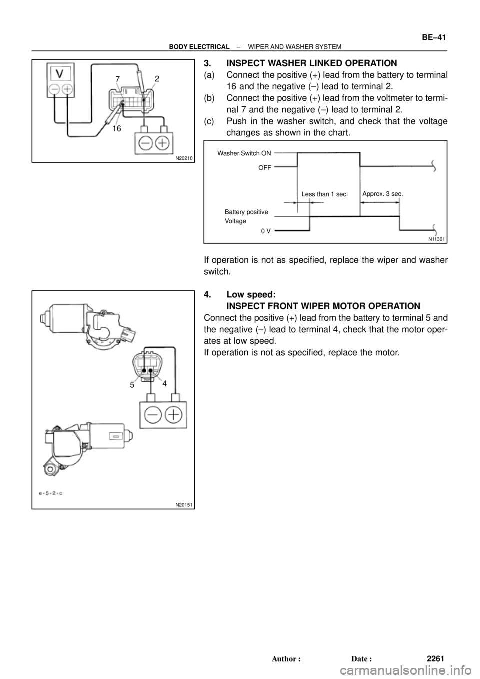
3. INSPECT WASHER LINKED OPERATION
(a) Connect the positive (+) lead from the battery to terminal
16 and the negative (±) lead to terminal 2.
(b) Connect the positive (+) lead from the voltmeter to termi-
nal 7 and the negative (±) lead to terminal 2.
(c) Push in the washer switch, and check that the voltage
changes as shown in the chart.
If operation is not as specified, replace the wiper and washer
switch.
4. Low speed:
INSPECT FRONT WIPER MOTOR OPERATION
Connect the positive (+) lead from the battery to terminal 5 and
the negative (±) lead to terminal 4, check that the motor oper-
ates at low speed.
If operation is not as specified, replace the motor.
Page 758 of 4592
N20152
3
4
N20153
5
4 BE±42
± BODY ELECTRICALWIPER AND WASHER SYSTEM
2262 Author�: Date�:
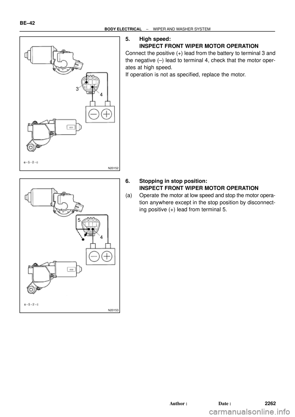
5. High speed:
INSPECT FRONT WIPER MOTOR OPERATION
Connect the positive (+) lead from the battery to terminal 3 and
the negative (±) lead to terminal 4, check that the motor oper-
ates at high speed.
If operation is not as specified, replace the motor.
6. Stopping in stop position:
INSPECT FRONT WIPER MOTOR OPERATION
(a) Operate the motor at low speed and stop the motor opera-
tion anywhere except in the stop position by disconnect-
ing positive (+) lead from terminal 5.
Page 759 of 4592
N20154
2 3
4
5
N20155
1 2
12
± BODY ELECTRICALWIPER AND WASHER SYSTEM
BE±43
2263 Author�: Date�:
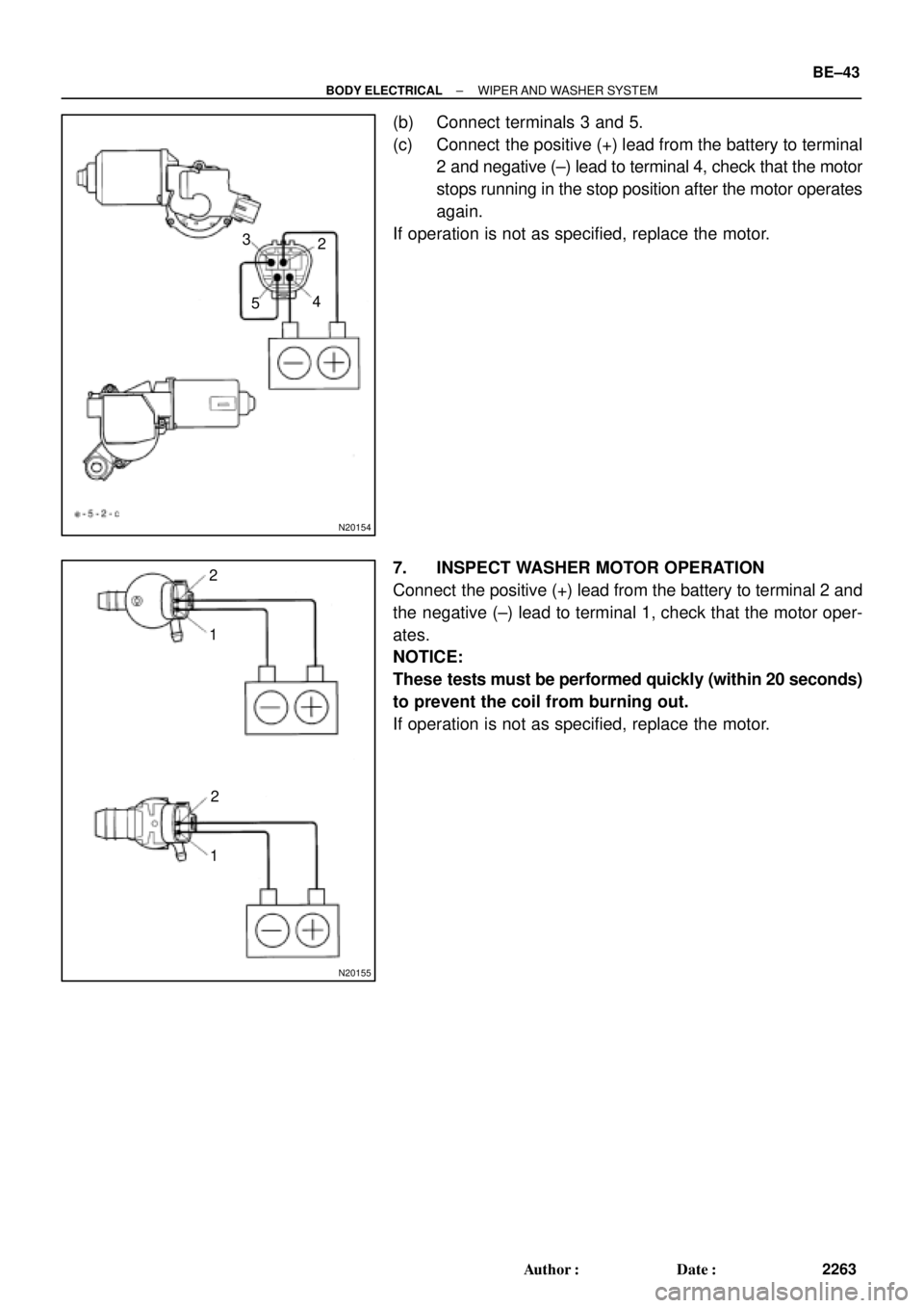
(b) Connect terminals 3 and 5.
(c) Connect the positive (+) lead from the battery to terminal
2 and negative (±) lead to terminal 4, check that the motor
stops running in the stop position after the motor operates
again.
If operation is not as specified, replace the motor.
7. INSPECT WASHER MOTOR OPERATION
Connect the positive (+) lead from the battery to terminal 2 and
the negative (±) lead to terminal 1, check that the motor oper-
ates.
NOTICE:
These tests must be performed quickly (within 20 seconds)
to prevent the coil from burning out.
If operation is not as specified, replace the motor.
Page 829 of 4592

I01475
25 Noise NOISE PRODUCED WHEN ENGINE STARTS
Whistling noise which becomes high±pitched when
accelerator strongly depressed, disappears shortly
after engine stops.Generator noise.
Whining noise occurs when A/C is operating. A/C noise.
Scratching noise occurs during sudden acceleration,
driving on rough roads or when ignition switch is turned
on.Fuel gauge noise.
Clicking sound heard when horn button is pressed,
then released. Whirring/ grating sound when pressed
continuously.Horn noise.
Murmuring sound stops when engine stops. Ignition noise.Ye s
No
No
No
No
NoYe s
Ye s
Ye s
Ye s
Tick±tock noise occurs in co±ordination with
blinking of flasher.
Noise occurs during window washer operation. Washer noise.Turn signal noise.
No
NoYe s
Ye s
Scratching noise occurs while engine is running
and continues for a while even after engine stops.
Scraping noise in time with wiper beat.Engine coolant temp. gauge noise.
Wiper noise.
Other type of noise.No
NoYe s
Ye s
± BODY ELECTRICALAUDIO SYSTEM
BE±113
2333 Author�: Date�:
Page 879 of 4592
BO0LK±01
N21119
Wiper MotorCowl Louver RH
Cowl Louver LH
Wiper Motor
Assembly
Window
Washer Nozzle
N´m (kgf´cm, ft´lbf) : Specified torqueWeatherstripWiper
Arms
Wiper
Link
24 (245, 18)
5.5 (55, 49 in.´lbf)
± BODYFRONT WIPER AND WASHER
BO±35
2383 Author�: Date�:
FRONT WIPER AND WASHER
COMPONENTS
Page 880 of 4592
BO0LL±01
N20998
BO4391
BO±36
± BODYFRONT WIPER AND WASHER
2384 Author�: Date�:
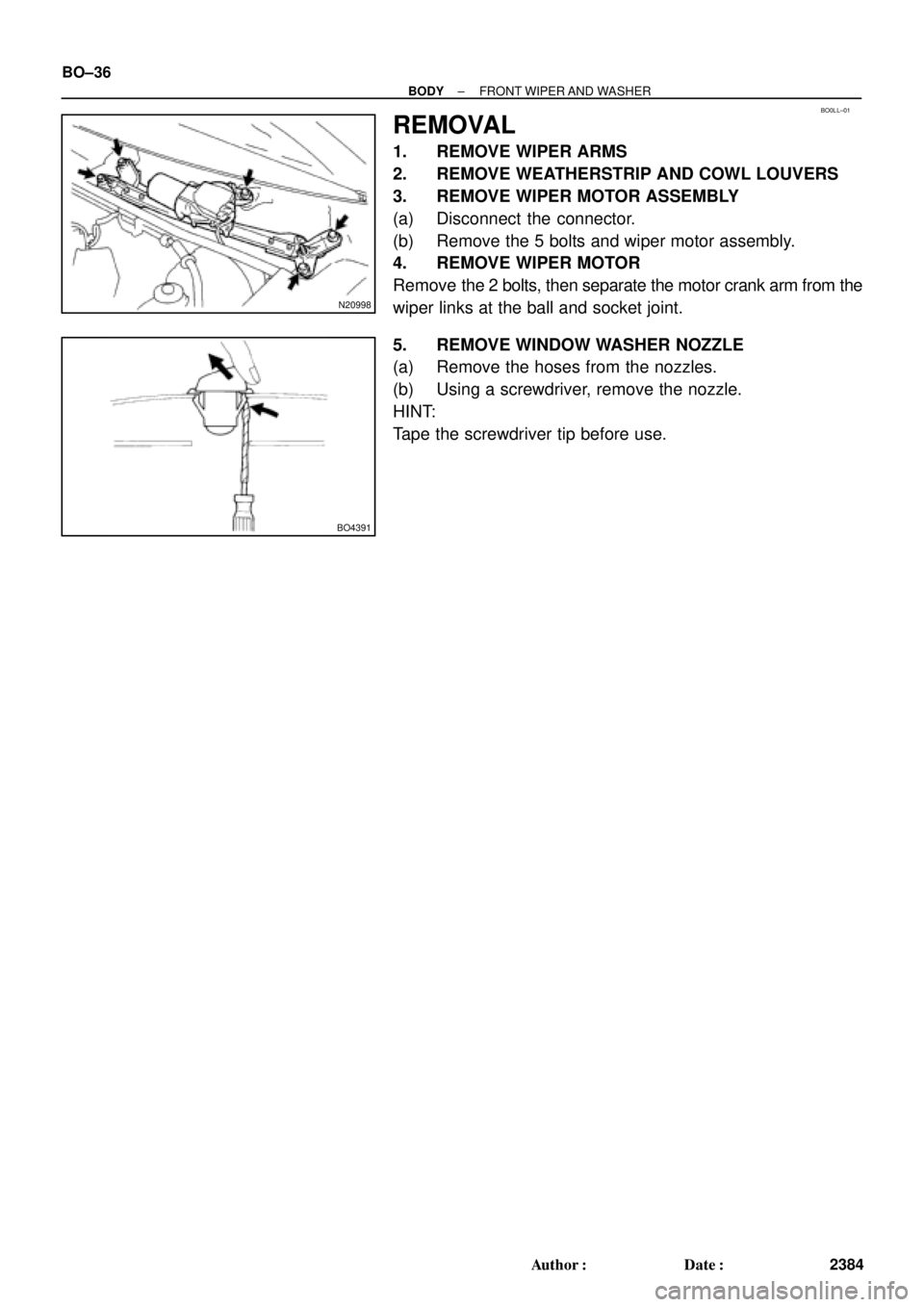
REMOVAL
1. REMOVE WIPER ARMS
2. REMOVE WEATHERSTRIP AND COWL LOUVERS
3. REMOVE WIPER MOTOR ASSEMBLY
(a) Disconnect the connector.
(b) Remove the 5 bolts and wiper motor assembly.
4. REMOVE WIPER MOTOR
Remove the 2 bolts, then separate the motor crank arm from the
wiper links at the ball and socket joint.
5. REMOVE WINDOW WASHER NOZZLE
(a) Remove the hoses from the nozzles.
(b) Using a screwdriver, remove the nozzle.
HINT:
Tape the screwdriver tip before use.
Page 881 of 4592
BO0LM±01
H01773
D
CB
C
AE
F B
B
A B
U.S.
H01774
D
C B
AB
FG
H E
ºaººbº
Canada
BE3367
2 ± 2.5 mm
(0.079 ± 0.098 in.)
0.7 ± 0.75 mm
(0. 028 ± 0.030 in.)
± BODYFRONT WIPER AND WASHER
BO±37
2385 Author�: Date�:
ADJUSTMENT
1. INSPECT WASHER NOZZLE
(a) While operating the washer, check that the washer fluid
hits the windshield and the upsurge area within the
shaded areas.
U.S. mm (in.)Canada mm (in.), Approx.
ºAº280 (11)600 (23.6)
ºBº150 (5.9)150 (5.9)
ºCº50 (2.0)250 (9.8)
ºDº50 (2.0) Max
ºEº180 (7.1)360 (14)
ºFº395 (15.5)114 (4.5)
ºGº 90 (3.5)
ºHº 474 (18.7)
ºIº 350 (13.8)
(b) Canadian models:
Adust the nozzle so the outboard points ºaº and ºbº are
within the wipe pattern.
(c) Check if the lower point where the washer fluid hits the
windshield is within the range of the wiping pattern (the
area of the glass the wiper blades wipe).
2. ADJUST WASHER NOZZLE
Using a tool like that shown in the illustration, rotate the nozzle
to adjust the fluid direction against the windshield.
Page 882 of 4592
BO0LN±01
N20998
H01772
ºAººAº
Cowl Louver Edge
BO±38
± BODYFRONT WIPER AND WASHER
2386 Author�: Date�:
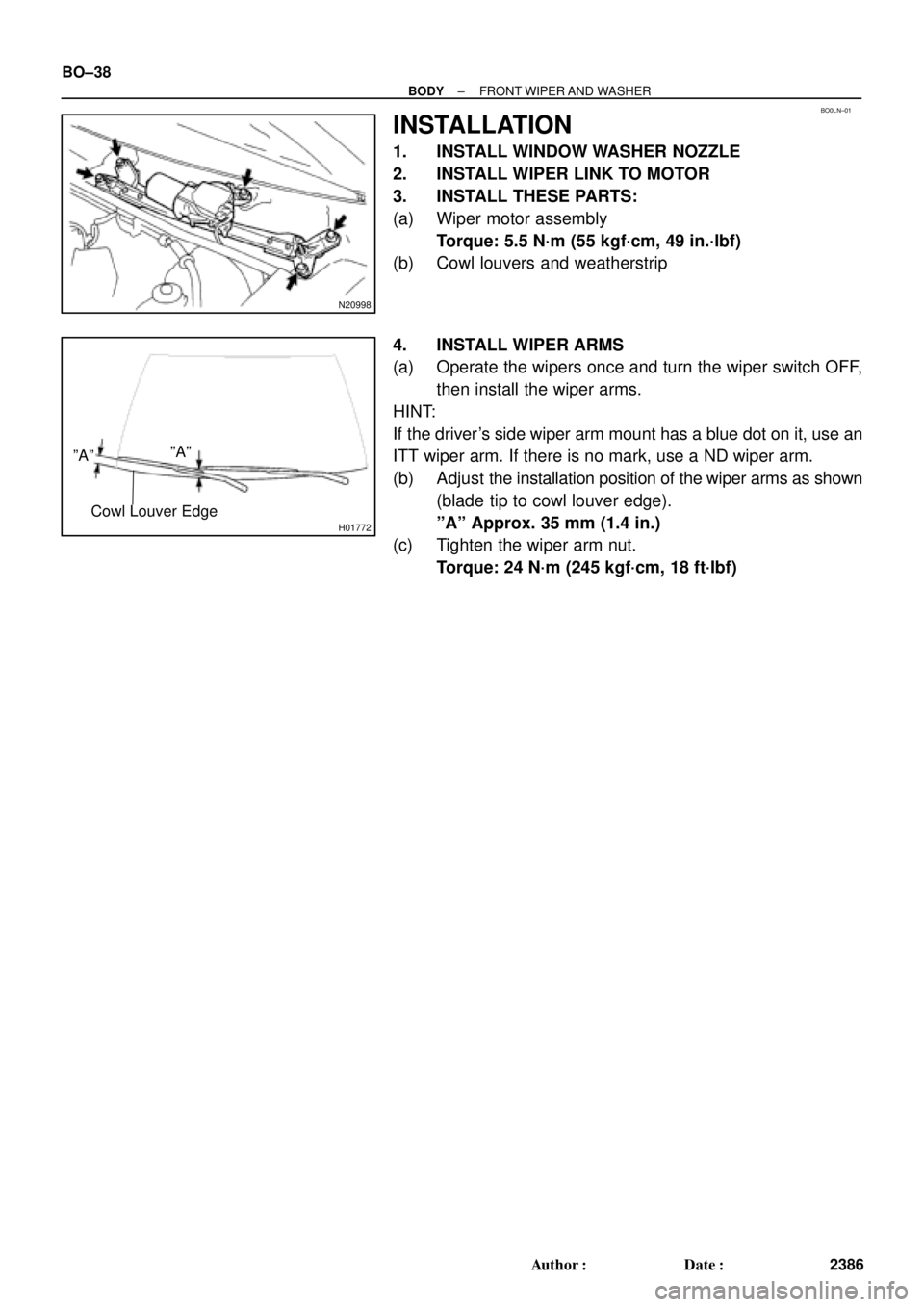
INSTALLATION
1. INSTALL WINDOW WASHER NOZZLE
2. INSTALL WIPER LINK TO MOTOR
3. INSTALL THESE PARTS:
(a) Wiper motor assembly
Torque: 5.5 N´m (55 kgf´cm, 49 in.´lbf)
(b) Cowl louvers and weatherstrip
4. INSTALL WIPER ARMS
(a) Operate the wipers once and turn the wiper switch OFF,
then install the wiper arms.
HINT:
If the driver's side wiper arm mount has a blue dot on it, use an
ITT wiper arm. If there is no mark, use a ND wiper arm.
(b) Adjust the installation position of the wiper arms as shown
(blade tip to cowl louver edge).
ºAº Approx. 35 mm (1.4 in.)
(c) Tighten the wiper arm nut.
Torque: 24 N´m (245 kgf´cm, 18 ft´lbf)
 : Specified torqueWeatherstripWiper
Arms
Wiper
Link
24 (245, 18)
5.5 (55, 49")

0.7 ± 0.75 mm
(0. 028 ± 0.030 in.)
± BODYFRONT WIPER AND WASHER
BO±37
238")