Page 7 of 4592

I01390
Condition: Insufficient cooling
I01392
Condition: Insufficient cooling
NOTE : These gauge indica-
tions are shown when the
refrigeration system has
been opened and the refrig-
erant charged without vacu-
um purging.
± AIR CONDITIONINGAIR CONDITIONING SYSTEM
AC±7
2489 Author�: Date�:
(6) Refrigerant overcharged or insufficient cooling of
condenser
Symptom seen in
refrigeration systemProbable causeDiagnosisRemedy
� Pressure too high on both low
and high pressure sides
� No air bubbles seen through the
sight glass even when the engine
rpm is lowered� Unable to develop sufficient per-
formance due to excessive refrig-
eration system
� Insufficient cooling of condenser� Excessive refrigerant in
cycle " refrigerant over charged
� Condenser cooling " condenser
fins clogged of condenser fan
faulty
(1) Clean condenser
(2) Check condenser fan motor
operation
(3) If (1) and (2) are in normal
state, check amount of refrigerant
Charge proper amount of refriger-
ant
(7) Air present in refrigeration system
Symptom seen in
refrigeration systemProbable causeDiagnosisRemedy
� Pressure too high on both low
and high pressure sides
� The low pressure piping hot to
touch
� Bubbles seen in sight glass
Air entered in refrigeration system
� Air present in refrigeration sys-
tem
� Insufficient vacuum purging
(1) Check compressor oil to see if
it is dirty or insufficient
(2) Evacuate air and charge new
refrigerant
Page 9 of 4592

± AIR CONDITIONINGAIR CONDITIONING SYSTEM
AC±9
2491 Author�: Date�:
3. INSPECT IDLE±UP SPEED
(a) Warm up engine.
(b) Inspect idle±up speed when the these conditions are es-
tablished.
�Warm up engine
�Blower speed control switch at ºHIº position
�A/C switch ON
�Temperature control dial at ºCOOLº position
Magnetic clutch conditionIdle±up speed
Magnetic clutch not engaged700 ± 50 rpm
Magnetic clutch engaged700 ± 50 rpm
If idle speed is not as specified, check ISC valve and air intake
system.
4. INSPECT FOR LEAKAGE OF REFRIGERANT
(a) Perform in these conditions:
�Stop engine.
�Secure good ventilation (If not the gas leak detector
may react to volatile gases witch are not refrigerant,
such as evaporated gasoline and exhaust gas.)
�Repeat the test 2 or 3 times.
�Make sure that there is some refrigerant remaining
in the refrigeration system.
When compressor is OFF: approx. 392 ± 588 kPa
(4 ± 6 kgf/ cm
2, 57 ± 85 psi)
(b) Bring the gas leak detector close to the drain hose before
performing the test.
HINT:
�After the blower motor stopped, leave the cooling unit for
more than 15 minutes.
�Expose the gas leak detector sensor the under the drain
hose.
�When bring the gas leak detector close to the drain hose,
make sure that the gas leak detector does not react to the
volatile gases.
If such reaction is unavoidable, the vehicle must be lifted up.
(c) If gas leak is not detected on the drain hose, remove the
blower resistor from the cooling unit. Then insert the gas
leak detector sensor into the unit and perform the test.
(d) Disconnect the connector and leave the pressure switch
for approx. 20 minutes. Then bring the gas leak detector
close to the pressure switch and perform the test.
(e) Bring the gas leak detector close to the refrigerant lines
and perform the test.
Page 13 of 4592
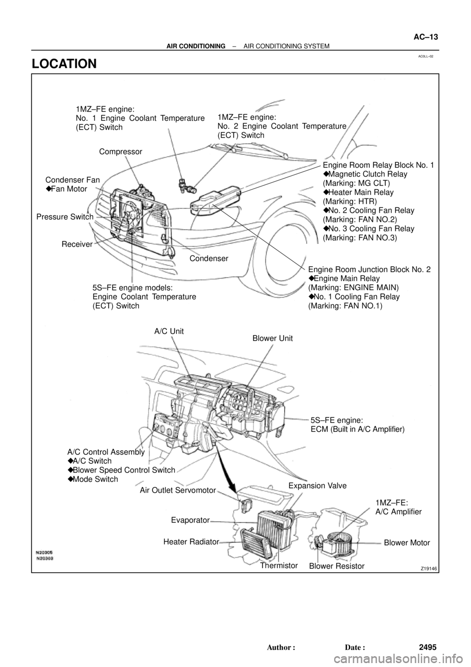
AC0LL±02
Z19146
1MZ±FE engine:
No. 1 Engine Coolant Temperature
(ECT) Switch
Compressor
Engine Room Junction Block No. 2
� Engine Main Relay
(Marking: ENGINE MAIN)
� No. 1 Cooling Fan Relay
(Marking: FAN NO.1)Engine Room Relay Block No. 1
� Magnetic Clutch Relay
(Marking: MG CLT)
� Heater Main Relay
(Marking: HTR)
� No. 2 Cooling Fan Relay
(Marking: FAN NO.2)
� No. 3 Cooling Fan Relay
(Marking: FAN NO.3)
5S±FE engine models:
Engine Coolant Temperature
(ECT) Switch Receiver Pressure SwitchCondenser Fan
� Fan Motor1MZ±FE engine:
No. 2 Engine Coolant Temperature
(ECT) Switch
Condenser
Blower Unit A/C Unit
A/C Control Assembly
� A/C Switch
� Blower Speed Control Switch
� Mode Switch
Air Outlet Servomotor
Heater Radiator
Thermistor
Blower ResistorBlower Motor 1MZ±FE:
A/C Amplifier Expansion Valve5S±FE engine:
ECM (Built in A/C Amplifier)
Evaporator
± AIR CONDITIONINGAIR CONDITIONING SYSTEM
AC±13
2495 Author�: Date�:
LOCATION
Page 14 of 4592

AC21T±01
AC±14
± AIR CONDITIONINGTROUBLESHOOTING
2496 Author�: Date�:
TROUBLESHOOTING
PROBLEM SYMPTOMS TABLE
Use the table below to help you find the cause of the problem. The numbers indicate the priority of the likely
cause of the problem. Check each part in order. If necessary, replace these parts.
SymptomSuspect AreaSee page
No blower operation
4. HTR Fuse
5. Heater main relay
6. Blower motor
7. Blower resistor
8. Blower speed control switch
9. Wire harness±
AC±70
AC±63
AC±64
AC±84
±
No air temperature control1. Engine coolant volume
2. A/C control assembly±
AC±80
No air inlet control1. A/C control assemblyAC±80
No air outlet control
1. HTR Fuse
2. Air outlet servomotor
3. Mode switch±
AC±65
AC±84
No compressor operation
1. Refrigerant volume
2. A.C Fuse
3. HTR Fuse
4. Magnetic clutch relay
5. Magnetic clutch
6. Compressor
7. Pressure switch
8. Heater main relay
9. Blower speed control switch
10.A/C switch
11. *1 ECM
*
2 A/C amplifier
12.Wire harness
AC±3
±
±
AC±71
AC±39
AC±39
AC±67
AC±70
AC±84
AC±84
DI±218
AC±88
±
No compressor operates intermittently
1. Refrigerant volume
2. Condenser fan
3. Pressure switch
4. *1 ECM
*2 A/C amplifier
5. Thermistor
6. Wire harnessAC±3
AC±74
AC±67
DI±218
AC±88
AC±24
±
No cool air comes out
1. Refrigerant volume
2. Refrigerant pressure
3. Drive belt
4. Compressor lock sensor
5. Magnetic clutch
6. Compressor
7. Pressure switch
8. Thermistor
9. A/C switch
10.*1 ECM
*2 A/C amplifier
11. Wire harnessAC±3
AC±3
AC±16
AC±16
AC±39
AC±39
AC±67
AC±24
AC±84
DI±218
AC±88
±
Page 15 of 4592

± AIR CONDITIONINGTROUBLESHOOTING
AC±15
2497 Author�: Date�:
Cool air comes out only at high engine rpm
1. Refrigerant volume
2. Drive belt
3. Magnetic clutch
4. Compressor
5. Condenser
6. Condenser fan
7. Receiver
8. Expansion valve
9. Evaporator
10.Thermistor
11. Refrigerant line
12.Pressure switch
13.*
1 ECM
*2 A/C amplifier
AC±3
AC±16
AC±16
AC±39
AC±52
AC±74
AC±49
AC±59
AC±30
AC±24
AC±21
AC±67
DI±218
AC±88
No engine idle±up when A/C switch ON
1. *1 ECM
*2 A/C amplifier
2. Wire harness
DI±218
AC±88
±
Blinking of A/C indicator
1. *1 ECM
*2 A/C amplifier
2. Thermistor
3. Compressor
DI±218
AC±88
AC±24
AC±39
A/C indicator does not lights up when turn mode switch to DEF.
position
1. A/C Fuse
2. Mode switch
3. A/C switch
4. *
1 ECM
*2 A/C amplifier
5. Wire harness
±
AC±84
AC±84
DI±218
AC±88
±
No warm air comes out
1. Engine coolant volume
2. A/C control assembly
3. Heater radiator±
AC±80
AC±57
No condenser fan operation
1. CDS FAN Fuse
2. Engine main relay
3. Cooling fan relay No. 1
4. Cooling fan relay No. 2
5. Cooling fan relay No. 3
6. Condenser fan motor
7. Pressure switch
8. *
1 Engine coolant temp. switch
*2 No. 1 Engine coolant temp. switch
9. *2No. 2 Engine coolant temp. switch
10.Wire harness
±
±
AC±72
AC±72
AC±72
AC±74
AC±67
AC±92
AC±92
AC±92
±
*1: 5S±FE Engine Models
*
2: 1MZ±FE Engine Models
Page 25 of 4592
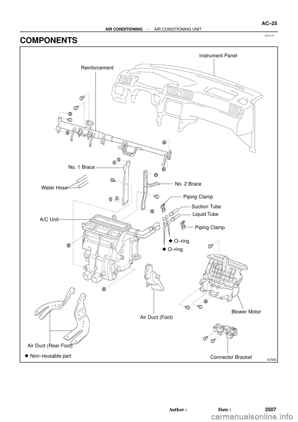
AC21V±01
I07050
ReinforcementInstrument Panel
No. 1 Brace
No. 2 Brace
A/C Unit
Piping Clamp
Suction Tube
Liquid Tube
Piping Clamp
� O±ring� O±ring
Air Duct (Rear Foot)
Air Duct (Foot)Blower Motor
Connector Bracket � Non±reusable partWater Hose
± AIR CONDITIONINGAIR CONDITIONING UNIT
AC±25
2507 Author�: Date�:
COMPONENTS
Page 26 of 4592
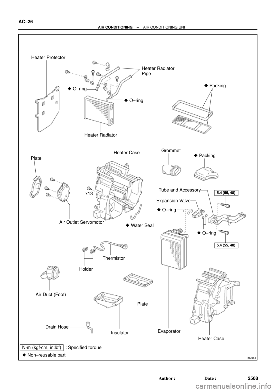
I07051
Heater Protector
Heater Radiator
Pipe
� Packing
� O±ring
� O±ring
Heater Radiator
Plate
Heater CaseGrommet
� Packing
x13
Air Outlet Servomotor� Water Seal
Air Duct (Foot)
Holder
Thermistor
5.4 (55, 48)
5.4 (55, 48)
� O±ring
� O±ring
Tube and Accessory
Expansion Valve
Drain Hose
Insulator
Plate
Evaporator
Heater Case
N´m (kgf´cm, in:lbf) : Specified torque
� Non±reusable part
AC±26
± AIR CONDITIONINGAIR CONDITIONING UNIT
2508 Author�: Date�:
Page 29 of 4592
AC21X±01
N20287
N20283
N20243
x13Water Seal
Plate
EvaporatorInsurator
N20293
± AIR CONDITIONINGAIR CONDITIONING UNIT
AC±29
2511 Author�: Date�:
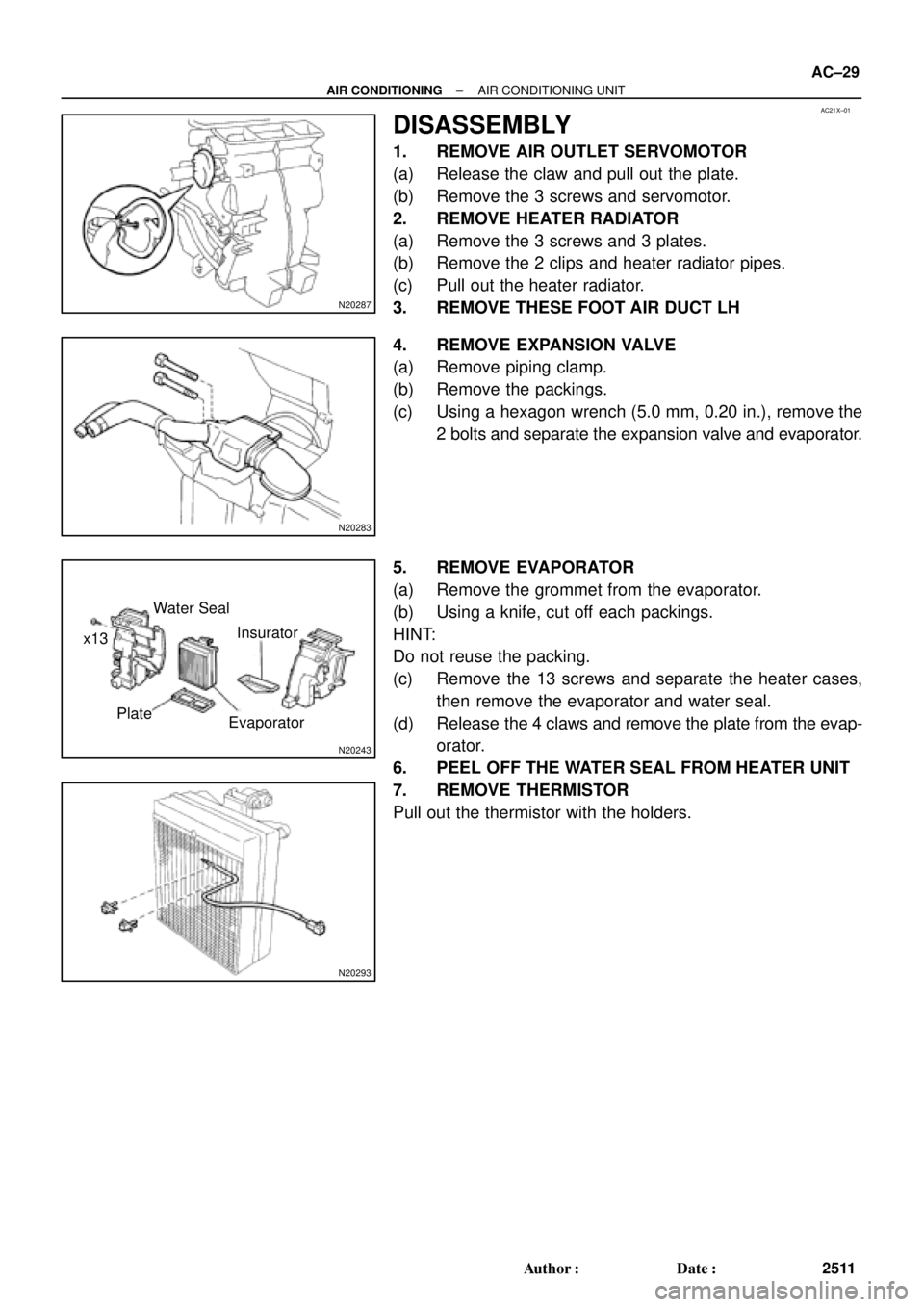
DISASSEMBLY
1. REMOVE AIR OUTLET SERVOMOTOR
(a) Release the claw and pull out the plate.
(b) Remove the 3 screws and servomotor.
2. REMOVE HEATER RADIATOR
(a) Remove the 3 screws and 3 plates.
(b) Remove the 2 clips and heater radiator pipes.
(c) Pull out the heater radiator.
3. REMOVE THESE FOOT AIR DUCT LH
4. REMOVE EXPANSION VALVE
(a) Remove piping clamp.
(b) Remove the packings.
(c) Using a hexagon wrench (5.0 mm, 0.20 in.), remove the
2 bolts and separate the expansion valve and evaporator.
5. REMOVE EVAPORATOR
(a) Remove the grommet from the evaporator.
(b) Using a knife, cut off each packings.
HINT:
Do not reuse the packing.
(c) Remove the 13 screws and separate the heater cases,
then remove the evaporator and water seal.
(d) Release the 4 claws and remove the plate from the evap-
orator.
6. PEEL OFF THE WATER SEAL FROM HEATER UNIT
7. REMOVE THERMISTOR
Pull out the thermistor with the holders.