Page 589 of 4592

BE±8
± BODY ELECTRICALBODY ELECTRICAL SYSTEM
2228 Author�: Date�:
Shift indicator lights do not light up.
1. Bulb
2. Meter Circuit Plate
3. Park/Neutral Position Switch (A140E)
(A541E)
4. Wire Harness±
BE±46
DI±424
DI±479
±
Only one shift indicator does not light up.1. Bulb
2. Meter Circuit Plate±
BE±46
Malfunction indicator light does not light up.
1. Bulb
2. ECM
3. Meter Circuit Plate
4. Wire Harness±
±
BE±46
±
SLIP indicator light does not light up.
1. Bulb
2. Traction ECU
3. Meter Circuit Plate
4. Wire Harness±
±
BE±46
±
TRAC OFF indicator light does not light up.
1. Bulb
2. Traction ECU
3. Meter Circuit Plate
4. Wire Harness±
±
BE±46
±
Security indicator light does not light up.
1. Bulb
2. Security ECU
3. Meter Circuit Plate
4. Wire Harness±
±
BE±46
±
Indicator lights do not light up. (Except Turn, Hi±beam and
security)1. GAUGE Fuse (I/P J/B No.1)
2. Wire Harness±
±
DEFOGGER SYSTEM
SymptomSuspect AreaSee page
All defogger systems do not operate.
1. DEFOG M±Fuse (I/P J/B No.1)
2. HTR Fuse (I/P J/B No.1)
3. Defogger Relay (I/P J/B No.1)
4. Defogger Switch
5. Wire Harness±
±
BE±56
BE±56
±
Rear window defogger does not operate.
1. Defogger Wire
2. Choke Coil
3. Wire HarnessBE±56
±
±
Mirror defogger does not operate.
1. MIR/HTR Fuse (I/P J/B No.1)
2. Mirror Defogger
3. Wire Harness±
BE±56
±
POWER WINDOW CONTROL SYSTEM
SymptomSuspect AreaSee page
Power window does not operate (ALL).
(Power Door Lock does not operate)1. POWER M±Fuse (I/P J/B No.1)
2. Power Main Relay (I/P J/B No.1)
3. Wire Harness±
BE±60
±
Power window does not operate (ALL).
(Power Door Lock is normal)1. Ignition Switch
2. Power Window Master Switch
3. Wire HarnessBE±14
BE±60
±
ºOne Touch Power Window Systemº does not operate.1. Power Window Master SwitchBE±60
Only one window glass does not move.
1. Power Window Master Switch
2. Power Window Switch
3. Power Window Motor
4. Wire HarnessBE±60
BE±60
BE±60
±
ºWindow Lock Systemº does not operate.1. Power Window Master SwitchBE±60
Page 591 of 4592

BE±10
± BODY ELECTRICALBODY ELECTRICAL SYSTEM
2230 Author�: Date�:
POWER SEAT CONTROL SYSTEM
SymptomSuspect AreaSee page
Power seat does not operate.
(Door lock system does not operate)1. POWER M±Fuse (I/P J/B No.1)
2. Wire Harness±
±
Power seat does not operate.
(Door lock system is normal)1. Power Seat Swtich (D,P)
2. Wire HarnessBE±78
±
ºSlide operationº does not operate.
1. Power Seat Switch (D, P)
2. Wire Harness
3. Slide Motor (D, P)BE±78
±
BE±78
ºLifter Operationº does not operate.
1. Power Seat Switch (D, P)
2. Wire Harness
3. Lifter Motor (D, P)BE±78
±
BE±78
ºReclining Operationº does not operate.
1. Power Seat Switch (D, P)
2. Wire Harness
3. Reclining Motor (D, P)BE±78
±
BE±78
(D): Driver's seat
(P): Passenger's seat
POWER MIRROR CONTROL SYSTEM
SymptomSuspect AreaSee page
Mirror does not operate.
1. CIG Fuse (I/P J/B No.1)
2. Mirror Switch
3. Mirror Motor
4. Wire Harness±
BE±83
BE±83
±
Mirror operates abnormally.
1. Mirror Switch
2. Mirror Motor
3. Wire HarnessBE±83
BE±83
±
Page 636 of 4592
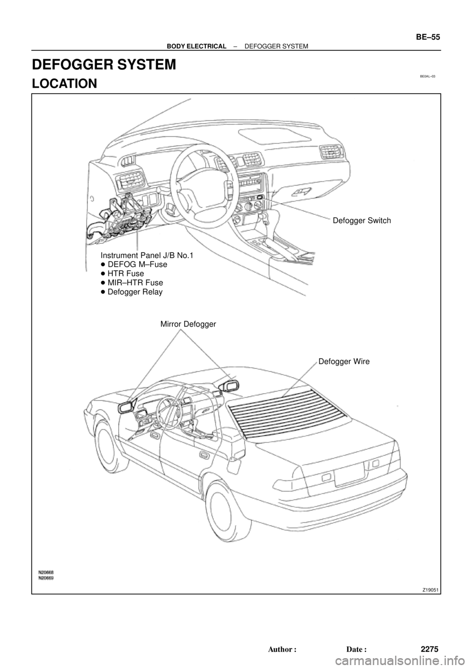
BE0AL±03
Z19051
Defogger Switch
Instrument Panel J/B No.1
� DEFOG M±Fuse
� HTR Fuse
� MIR±HTR Fuse
� Defogger Relay
Mirror Defogger
Defogger Wire
± BODY ELECTRICALDEFOGGER SYSTEM
BE±55
2275 Author�: Date�:
DEFOGGER SYSTEM
LOCATION
Page 638 of 4592
N21371
6
4
BE4029
Tester Probe
Tin FoilHeat Wire
BE0123
At Center
BE0124
0 VoltSeveral
Volts
Broken
Wire
± BODY ELECTRICALDEFOGGER SYSTEM
BE±57
2277 Author�: Date�:
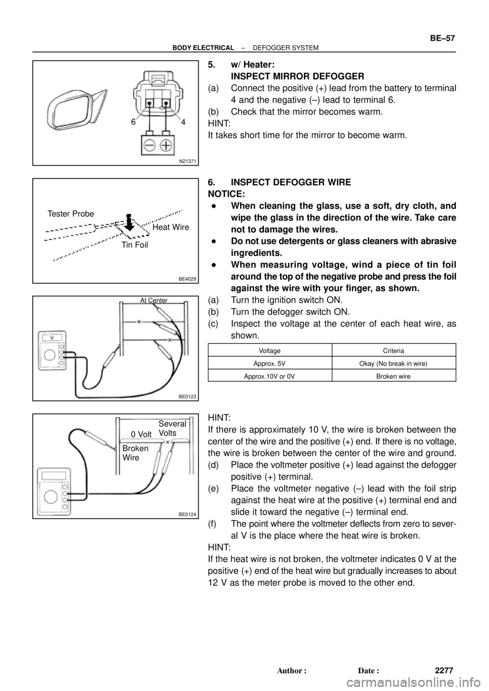
5. w/ Heater:
INSPECT MIRROR DEFOGGER
(a) Connect the positive (+) lead from the battery to terminal
4 and the negative (±) lead to terminal 6.
(b) Check that the mirror becomes warm.
HINT:
It takes short time for the mirror to become warm.
6. INSPECT DEFOGGER WIRE
NOTICE:
�When cleaning the glass, use a soft, dry cloth, and
wipe the glass in the direction of the wire. Take care
not to damage the wires.
�Do not use detergents or glass cleaners with abrasive
ingredients.
�When measuring voltage, wind a piece of tin foil
around the top of the negative probe and press the foil
against the wire with your finger, as shown.
(a) Turn the ignition switch ON.
(b) Turn the defogger switch ON.
(c) Inspect the voltage at the center of each heat wire, as
shown.
VoltageCriteria
Approx. 5VOkay (No break in wire)
Approx.10V or 0VBroken wire
HINT:
If there is approximately 10 V, the wire is broken between the
center of the wire and the positive (+) end. If there is no voltage,
the wire is broken between the center of the wire and ground.
(d) Place the voltmeter positive (+) lead against the defogger
positive (+) terminal.
(e) Place the voltmeter negative (±) lead with the foil strip
against the heat wire at the positive (+) terminal end and
slide it toward the negative (±) terminal end.
(f) The point where the voltmeter deflects from zero to sever-
al V is the place where the heat wire is broken.
HINT:
If the heat wire is not broken, the voltmeter indicates 0 V at the
positive (+) end of the heat wire but gradually increases to about
12 V as the meter probe is moved to the other end.
Page 663 of 4592
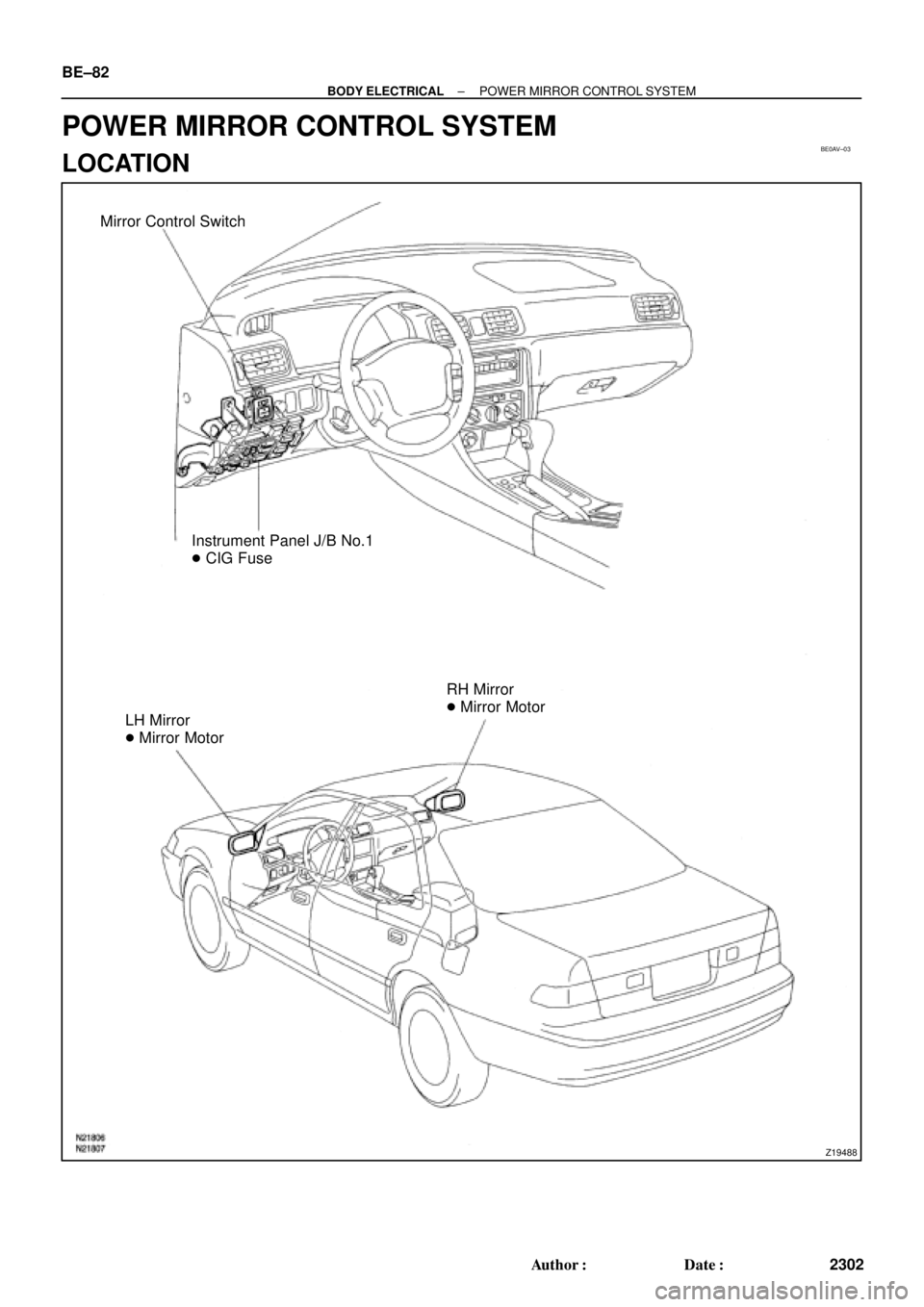
BE0AV±03
Z19488
Mirror Control Switch
Instrument Panel J/B No.1
� CIG Fuse
LH Mirror
� Mirror MotorRH Mirror
� Mirror Motor BE±82
± BODY ELECTRICALPOWER MIRROR CONTROL SYSTEM
2302 Author�: Date�:
POWER MIRROR CONTROL SYSTEM
LOCATION
Page 664 of 4592
BE0AW±03
Z16591
LR
MIRROR
OFF
LEFT SIDERIGHT SIDE
UP
OFF LEFT
RIGHT
DOWN
1 2 3
7 8 4
10 9 5
BE2357 h±10±2
6
N21184
TMMK made
(w/o Heater)
TMC made
(w/o Heater)TMMK made
(w/ Heater)1
2
2 332
± BODY ELECTRICALPOWER MIRROR CONTROL SYSTEM
BE±83
2303 Author�: Date�:
INSPECTION
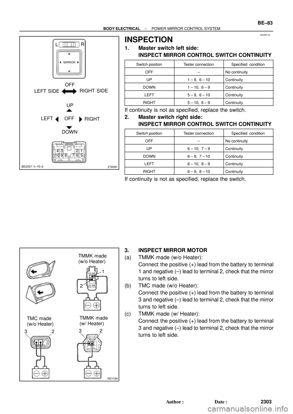
1. Master switch left side:
INSPECT MIRROR CONTROL SWITCH CONTINUITY
Switch positionTester connectionSpecified condition
OFF±No continuity
UP1 ± 9, 6 ± 10Continuity
DOWN1 ± 10, 6 ± 9Continuity
LEFT5 ± 9, 6 ± 10Continuity
RIGHT5 ± 10, 6 ± 9Continuity
If continuity is not as specified, replace the switch.
2. Master switch right side:
INSPECT MIRROR CONTROL SWITCH CONTINUITY
Switch positionTester connectionSpecified condition
OFF±No continuity
UP6 ± 10, 7 ± 9Continuity
DOWN6 ± 9, 7 ± 10Continuity
LEFT6 ± 10, 8 ± 9Continuity
RIGHT6 ± 9, 8 ± 10Continuity
If continuity is not as specified, replace the switch.
3. INSPECT MIRROR MOTOR
(a) TMMK made (w/o Heater):
Connect the positive (+) lead from the battery to terminal
1 and negative (±) lead to terminal 2, check that the mirror
turns to left side.
(b) TMC made (w/o Heater):
Connect the positive (+) lead from the battery to terminal
3 and negative (±) lead to terminal 2, check that the mirror
turns to left side.
(c) TMMK made (w/ Heater):
Connect the positive (+) lead from the battery to terminal
3 and negative (±) lead to terminal 2, check that the mirror
turns to left side.
Page 665 of 4592
N21185
TMMK made
(w/o Heater)
TMC made
(w/o Heater)TMMK made
(w/ Heater)
N21186
TMMK made
(w/o Heater)
TMC made
(w/o Heater)TMMK made
(w/ Heater) BE±84
± BODY ELECTRICALPOWER MIRROR CONTROL SYSTEM
2304 Author�: Date�:
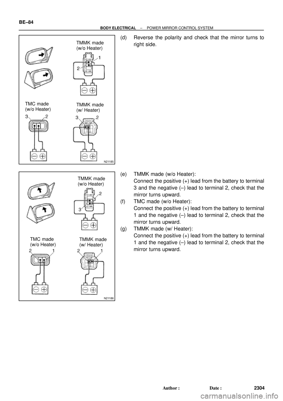
(d) Reverse the polarity and check that the mirror turns to
right side.
(e) TMMK made (w/o Heater):
Connect the positive (+) lead from the battery to terminal
3 and the negative (±) lead to terminal 2, check that the
mirror turns upward.
(f) TMC made (w/o Heater):
Connect the positive (+) lead from the battery to terminal
1 and the negative (±) lead to terminal 2, check that the
mirror turns upward.
(g) TMMK made (w/ Heater):
Connect the positive (+) lead from the battery to terminal
1 and the negative (±) lead to terminal 2, check that the
mirror turns upward.
Page 666 of 4592
N21187
TMMK made
(w/o Heater)
TMC made
(w/o Heater)TMMK made
(w/ Heater)
± BODY ELECTRICALPOWER MIRROR CONTROL SYSTEM
BE±85
2305 Author�: Date�:
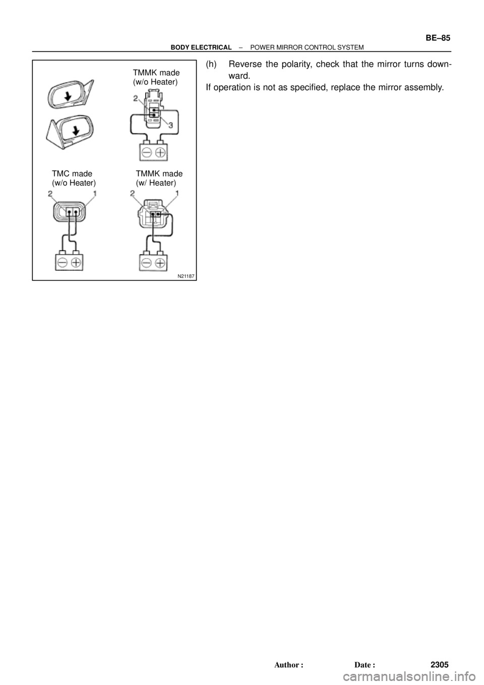
(h) Reverse the polarity, check that the mirror turns down-
ward.
If operation is not as specified, replace the mirror assembly.