Page 2053 of 4592
I00268
I00269
I00275
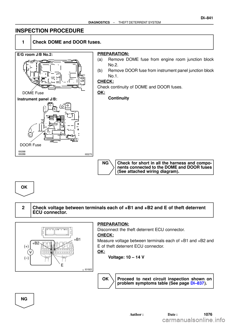
E/G room J/B No.2:
Instrument panel J/B:DOME Fuse
DOOR Fuse
I01922E+B1
+B2
(+)
(±)
± DIAGNOSTICSTHEFT DETERRENT SYSTEM
DI±841
1076 Author�: Date�:
INSPECTION PROCEDURE
1 Check DOME and DOOR fuses.
PREPARATION:
(a) Remove DOME fuse from engine room junction block
No.2.
(b) Remove DOOR fuse from instrument panel junction block
No.1.
CHECK:
Check continuity of DOME and DOOR fuses.
OK:
Continuity
NG Check for short in all the harness and compo-
nents connected to the DOME and DOOR fuses
(See attached wiring diagram).
OK
2 Check voltage between terminals each of +B1 and +B2 and E of theft deterrent
ECU connector.
PREPARATION:
Disconnect the theft deterrent ECU connector.
CHECK:
Measure voltage between terminals each of +B1 and +B2 and
E of theft deterrent ECU connector.
OK:
Voltage: 10 ± 14 V
OK Proceed to next circuit inspection shown on
problem symptoms table (See page DI±837).
NG
Page 2064 of 4592
I00269
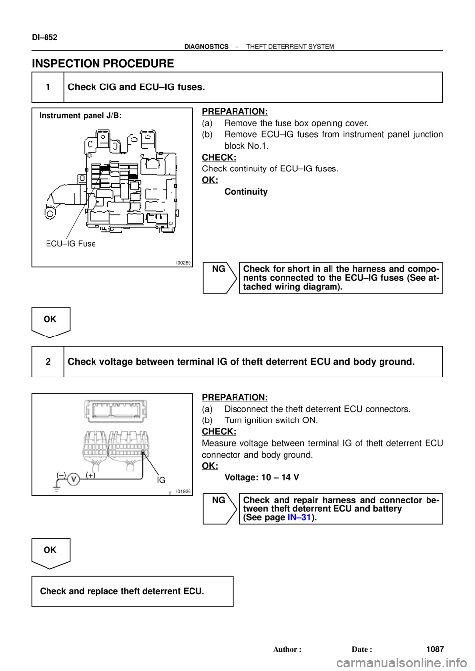
Instrument panel J/B:
ECU±IG Fuse
I01926
IG (+) (±)
DI±852
± DIAGNOSTICSTHEFT DETERRENT SYSTEM
1087 Author�: Date�:
INSPECTION PROCEDURE
1 Check CIG and ECU±IG fuses.
PREPARATION:
(a) Remove the fuse box opening cover.
(b) Remove ECU±IG fuses from instrument panel junction
block No.1.
CHECK:
Check continuity of ECU±IG fuses.
OK:
Continuity
NG Check for short in all the harness and compo-
nents connected to the ECU±IG fuses (See at-
tached wiring diagram).
OK
2 Check voltage between terminal IG of theft deterrent ECU and body ground.
PREPARATION:
(a) Disconnect the theft deterrent ECU connectors.
(b) Turn ignition switch ON.
CHECK:
Measure voltage between terminal IG of theft deterrent ECU
connector and body ground.
OK:
Voltage: 10 ± 14 V
NG Check and repair harness and connector be-
tween theft deterrent ECU and battery
(See page IN±31).
OK
Check and replace theft deterrent ECU.
Page 2095 of 4592

I00281
Cruise Control ECU
C15
G±B
2 1 34W±B
3
STOP Fuse8 Stop Light Switch
4
R±Y
Stop Lights Cruise Control Actuator
� Actuator Magnetic Clutch
J7
J7AAJ/C
W±B
1J
1J
W±B
A
J/C
IG 8
7
J11Instrument
Panel J/BL
± DIAGNOSTICSCRUISE CONTROL SYSTEM
DI±883
111 8 Author�: Date�:
DTC 12 Actuator Magnetic Clutch Circuit
CIRCUIT DESCRIPTION
This circuit turns on the magnetic clutch inside the actuator during cruise control operation according to the
signal from the ECU. If a malfunction occurs in the actuator or speed sensor, etc. during cruise control opera-
tion, the rotor shaft between the motor and control plate is released.
When the brake pedal is depressed, the stop light switch turns on, supplying electrical power to the stop light.
Power supply to the magnetic clutch is mechanically cut and the magnetic clutch is turned OFF.
When driving downhill, if the vehicle speed exceeds the set speed by 15 km/h (9 mph), the ECU turns the
safety magnet clutch OFF. If the vehicle speed later drops to within 10 km/h (6 mph), cruise control at the
set speed is resumed.
DTC No.Detection ItemTrouble Area
12Short in actuator magnetic clutch circuit.
Open (0.8 sec.) in actuator magnetic clutch circuit.
�STOP Fuse
�Stop light switch
�Actuator magnetic clutch
�Harness or connector between cruise control ECU and
actuator magnetic clutch, actuator magnetic clutch and body
ground
�Cruise control ECU
WIRING DIAGRAM
DI08N±12
Page 2100 of 4592

I00292
Vehicle Speed Sensor
ECUCombination Meter
Cruise Control ECU
4 pulses/
1 rotation
of rotor shaft4 pulses/
1 rotation
of rotor shaft
I00282
Cruise Control ECU
12
SPDV±W V±WB
BJ15
J/CIG3
3
V±W14
Combination Meter
15
6
Speedo
±meter
P L
IJ12IJ17
P
3L
2
SI
SE
IG+
1
R±Lto GAUGE Fuse
C15
C9 C9
C10
Speed
Sensor DI±888
± DIAGNOSTICSCRUISE CONTROL SYSTEM
1123 Author�: Date�:
DTC 21 Open in Vehicle Speed Sensor Circuit
CIRCUIT DESCRIPTION
The signal from the vehicle speed sensor circuit is sent to cruise control ECU as vehicle speed signal.
The rotor shaft is driven by the gear of the transmission.
For each rotation of the shaft, the vehicle speed sensor sends a 4±pulse signal through the combination
meter to the cruise control ECU (See the following installation).
This signal is converted inside the combination meter and sent as a 4±pulse signal to the cruise control ECU.
The ECU calculates the vehicle speed from this pulse frequency.
DTC No.Detection ItemTrouble Area
21Speed signal is not input to the cruise control ECU while cruise
control is set.
�Combination meter
�Harness or connector between cruise control ECU and com-
bination meter, combination meter and vehicle speed sensor
�Vehicle speed sensor
�Cruise control ECU
WIRING DIAGRAM
DI08P±12
Page 2110 of 4592

I00285
Cruise Control ECU
2
STP±
8
L
J27
J/C
G±W A A
G±W 5
1R
1R
G±W 1
4 Stop Light Switch
2
3
W
7
1C4
1BG±B 4
B±R
FL BLOCK
F91 1
F4
B±G
FL MAIN
BatteryR±Y
Cruise Control
Actuator
3
4 J/C
A
J7 A
J7
W±B
1J
1JJ/C
AJ11
W±B
IG Instrument Panel J/B
STOP
ALT
C15
C15
Instrument Panel J/B
Instrument Panel J/BW±B
87 DI±898
± DIAGNOSTICSCRUISE CONTROL SYSTEM
1133 Author�: Date�:
Stop Light Switch Circuit
CIRCUIT DESCRIPTION
When the brake pedal is depressed, the stop light switch sends a signal to the ECU. When the ECU receives
this signal, it cancels the cruise control.
A fail±safe function is provided so that the cancel functions normally, even if there is a malfunction in the stop
light signal circuit.
The cancel conditions are: Battery positive voltage at terminal STP±
When the brake is ON, battery positive voltage normally is applied through the STOP fuse and stop light
switch to terminal STP± of the ECU, and the ECU turns the cruise control OFF.
If the harness connected to terminal STP± has an open circuit, terminal STP± will have battery positive volt-
age and the cruise control will be turned OFF.
Also, when the brake is ON, the magnetic clutch circuit is cut mechanically by the stop light switch, turning
the cruise control OFF. (See page DI±883 for operation of the magnetic clutch)
WIRING DIAGRAM
DI08T±11
Page 2357 of 4592
F00073
ECU±IGECU±IG
Instrument
Panel J/BECU±IG
± DIAGNOSTICSANTI±LOCK BRAKE SYSTEM
DI±205
INSPECTION PROCEDURE
1 Check ECU±IG fuse.
PREPARATION:
Remove ECU±IG fuse from Instrument Panel J/B.
CHECK:
Check continuity of ECU±IG fuse.
OK:
Continuity
NG Check for short circuit in all the harness and
components connected to ECU±IG fuse (See at-
tached wiring diagram).
OK
2 Check battery positive voltage.
OK:
Voltage: 10 ± 14 V
NG Check and repair the charging system (See Pub.
No. RM654U on page CH±1).
OK
Page 2483 of 4592

I00281
Cruise Control ECU
C16
G±B
2 1 34W±B
3
STOP Fuse8 Stop Light Switch
4
R±Y
Stop Lights Cruise Control Actuator
� Actuator Magnetic Clutch
J6
J6AAJ/C
W±B
1J
1J
W±B
A
J/C
IF 8
7
J9Instrument
Panel J/BL
± DIAGNOSTICSCRUISE CONTROL SYSTEM
DI±331
DTC 12 Actuator Magnetic Clutch Circuit
CIRCUIT DESCRIPTION
This circuit turns on the magnetic clutch inside the actuator during cruise control operation according to the
signal from the ECU. If a malfunction occurs in the actuator or speed sensor, etc. during cruise control opera-
tion, the rotor shaft between the motor and control plate is released.
When the brake pedal is depressed, the stop light switch turns on, supplying electrical power to the stop light.
Power supply to the magnetic clutch is mechanically cut and the magnetic clutch is turned OFF.
When driving downhill, if the vehicle speed exceeds the set speed by 15 km/h (9 mph), the ECU turns the
safety magnet clutch OFF. If the vehicle speed later drops to within 10 km/h (6 mph), cruise control at the
set speed is resumed.
DTC No.DTC Detecting ConditionTrouble Area
12Short in actuator magnetic clutch circuit.
Open (0.8 sec.) in actuator magnetic clutch circuit.
�STOP Fuse
�Stop light switch
�Actuator magnetic clutch
�Harness or connector between cruise control ECU and
actuator magnetic clutch, actuator magnetic clutch and body
ground
�Cruise control ECU
WIRING DIAGRAM
DI08N±13
Page 2488 of 4592

I00292
Vehicle Speed Sensor
ECUCombination Meter
Cruise Control ECU
4 pulses/
1 rotation
of rotor shaft4 pulses/
1 rotation
of rotor shaft
I00282
Cruise Control ECU
12
SPDV±W V±WB
BJ15
J/CIF1
3
V±W14
Combination Meter
15
6
Speedo
±meter
P L
IH12IH17
P
3L
2
SI
SE
IG+
1
R±Lto GAUGE Fuse
C16
C11 C11
C12
Speed
Sensor DI±336
± DIAGNOSTICSCRUISE CONTROL SYSTEM
DTC 21 Open in Vehicle Speed Sensor Circuit
CIRCUIT DESCRIPTION
The signal from the vehicle speed sensor circuit is sent to cruise control ECU as vehicle speed signal.
The rotor shaft is driven by the gear of the transmission.
For each rotation of the shaft, the vehicle speed sensor sends a 4±pulse signal through the combination
meter to the cruise control ECU (See the following installation).
This signal is converted inside the combination meter and sent as a 4±pulse signal to the cruise control ECU.
The ECU calculates the vehicle speed from this pulse frequency.
DTC No.DTC Detecting ConditionTrouble Area
21Speed signal is not input to the cruise control ECU while cruise
control is set.
�Combination meter
�Harness or connector between cruise control ECU and com-
bination meter, combination meter and vehicle speed sensor
�Vehicle speed sensor
�Cruise control ECU
WIRING DIAGRAM
DI08P±13