Page 95 of 4592
AX034±01
± AUTOMATIC TRANSAXLE (A140E)AUTOMATIC TRANSAXLE SYSTEM
AX±1
1894 Author�: Date�:
AUTOMATIC TRANSAXLE SYSTEM
PRECAUTION
If the vehicle is equipped with a mobile communication system, refer to the precautions in the IN section.
Page 96 of 4592
AX035±01
D00989
O/D Direct
Clutch (C
0)O/D Brake (B0) 1st & Reverse Brake (B
3)
One ± Way clutch
No.2 (F
2)2nd Brake (B
2)
Forward
Clutch (C
1)2nd Coast brake (B
1)
Direct Clutch (C
2)
O/D One ± Way
Clutch (F
0)
O/D Planetary GearCounter
Drive Gear
Intermediate
ShaftRear
Planetary Gear One Way Clutch
No.1 (F1)
Front Planetary
GearInput Shaft
Shift lever
positionGear position
Parking
Reverse
Neutral P
R
NC
1B2B3F0C0C2B0B1F1F2
D
2
L1st
2nd
3rd
O/D
1st
2nd
*3rd
1st
*2nd� �
�
� �
�
� �
�
�
�� �
�
�
� �
�
�
��
�
��
��
�� ��� � � �
��
�
��� � �
�
�� �
�
�
� Planetary Gear Unit
�: Operating
*: Down±shift only in the 3rd gear for the 2 position and 2nd gear for the L position no up±shift. AX±2
± AUTOMATIC TRANSAXLE (A140E)AUTOMATIC TRANSAXLE SYSTEM
1895 Author�: Date�:
OPERATION
Page 97 of 4592
Q00207
AX036±01
Q04678
Drive GearVehicle Speed Sensor
O±Ring
Clip
± AUTOMATIC TRANSAXLE (A140E)VEHICLE SPEED SENSOR
AX±3
1896 Author�: Date�:
VEHICLE SPEED SENSOR
ON±VEHICLE REPAIR
1. REMOVE AIR CLEANER ASSEMBLY
2. DISCONNECT VEHICLE SPEED SENSOR CONNEC-
TOR
3. REMOVE VEHICLE SPEED SENSOR ASSEMBLY
(a) Remove the bolt and vehicle speed sensor assembly.
(b) Remove the clip and speedometer driven gear from ve-
hicle speed sensor.
(c) Remove the O±ring from vehicle speed sensor.
4. INSTALL VEHICLE SPEED SENSOR ASSEMBLY
(a) Coat a new O±ring with ATF and install it to the vehicle
speed sensor.
(b) Install the speedometer driven gear to the vehicle speed
sensor and clip.
(c) Install the vehicle speed sensor assembly and torque the
bolts.
Torque: 16 N´m (160 kgf´cm, 12 ft´lbf)
5. CONNECT VEHICLE SPEED SENSOR CONNECTOR
6. INSTALL AIR CLEANER ASSEMBLY
Page 98 of 4592
Q10050
AX037±01
AX±4
± AUTOMATIC TRANSAXLE (A140E)PARK/NEUTRAL POSITION (PNP) SWITCH
1897 Author�: Date�:
PARK/NEUTRAL POSITION (PNP)
SWITCH
ON±VEHICLE REPAIR
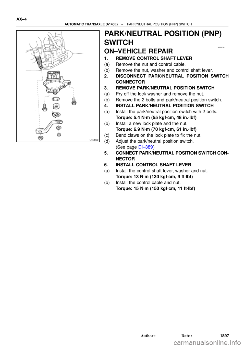
1. REMOVE CONTROL SHAFT LEVER
(a) Remove the nut and control cable.
(b) Remove the nut, washer and control shaft lever.
2. DISCONNECT PARK/NEUTRAL POSITION SWITCH
CONNECTOR
3. REMOVE PARK/NEUTRAL POSITION SWITCH
(a) Pry off the lock washer and remove the nut.
(b) Remove the 2 bolts and park/neutral position switch.
4. INSTALL PARK/NEUTRAL POSITION SWITCH
(a) Install the park/neutral position switch with 2 bolts.
Torque: 5.4 N´m (55 kgf´cm, 48 in.´lbf)
(b) Install a new lock plate and the nut.
Torque: 6.9 N´m (70 kgf´cm, 61 in.´lbf)
(c) Bend claws on the lock plate to fix the nut.
(d) Adjust the park/neutral position switch.
(See page DI±389)
5. CONNECT PARK/NEUTRAL POSITION SWITCH CON-
NECTOR
6. INSTALL CONTROL SHAFT LEVER
(a) Install the control shaft lever, washer and nut.
Torque: 13 N´m (130 kgf´cm, 9 ft´lbf)
(b) Install the control cable and nut.
Torque: 15 N´m (150 kgf´cm, 11 ft´lbf)
Page 99 of 4592
AX038±01
Q00073
AT0103
Z10944
mm (in.)
14 (0.551)36 (1.417)
AT2711
Z10940
20
(0.787)mm (in.)
45
(1.772)50
(1.969)
AT3336
± AUTOMATIC TRANSAXLE (A140E)VALVE BODY ASSEMBLY
AX±5
1898 Author�: Date�:
VALVE BODY ASSEMBLY
ON±VEHICLE REPAIR
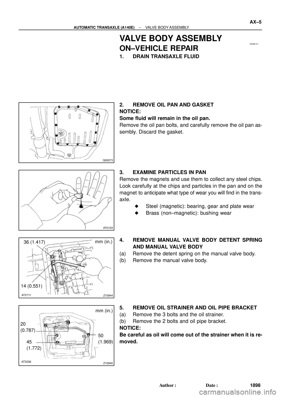
1. DRAIN TRANSAXLE FLUID
2. REMOVE OIL PAN AND GASKET
NOTICE:
Some fluid will remain in the oil pan.
Remove the oil pan bolts, and carefully remove the oil pan as-
sembly. Discard the gasket.
3. EXAMINE PARTICLES IN PAN
Remove the magnets and use them to collect any steel chips.
Look carefully at the chips and particles in the pan and on the
magnet to anticipate what type of wear you will find in the trans-
axle.
�Steel (magnetic): bearing, gear and plate wear
�Brass (non±magnetic): bushing wear
4. REMOVE MANUAL VALVE BODY DETENT SPRING
AND MANUAL VALVE BODY
(a) Remove the detent spring on the manual valve body.
(b) Remove the manual valve body.
5. REMOVE OIL STRAINER AND OIL PIPE BRACKET
(a) Remove the 3 bolts and the oil strainer.
(b) Remove the 2 bolts and oil pipe bracket.
NOTICE:
Be careful as oil will come out of the strainer when it is re-
moved.
Page 100 of 4592
Z10941 AT0493
AT7868
AT0399
OR0038
Z19291
16 (0.63)
Shift Solenoid
Valve No.1
16 (0.63)Shift Solenoid
Valve No.2
AT3008
mm (in.) AX±6
± AUTOMATIC TRANSAXLE (A140E)VALVE BODY ASSEMBLY
1899 Author�: Date�:
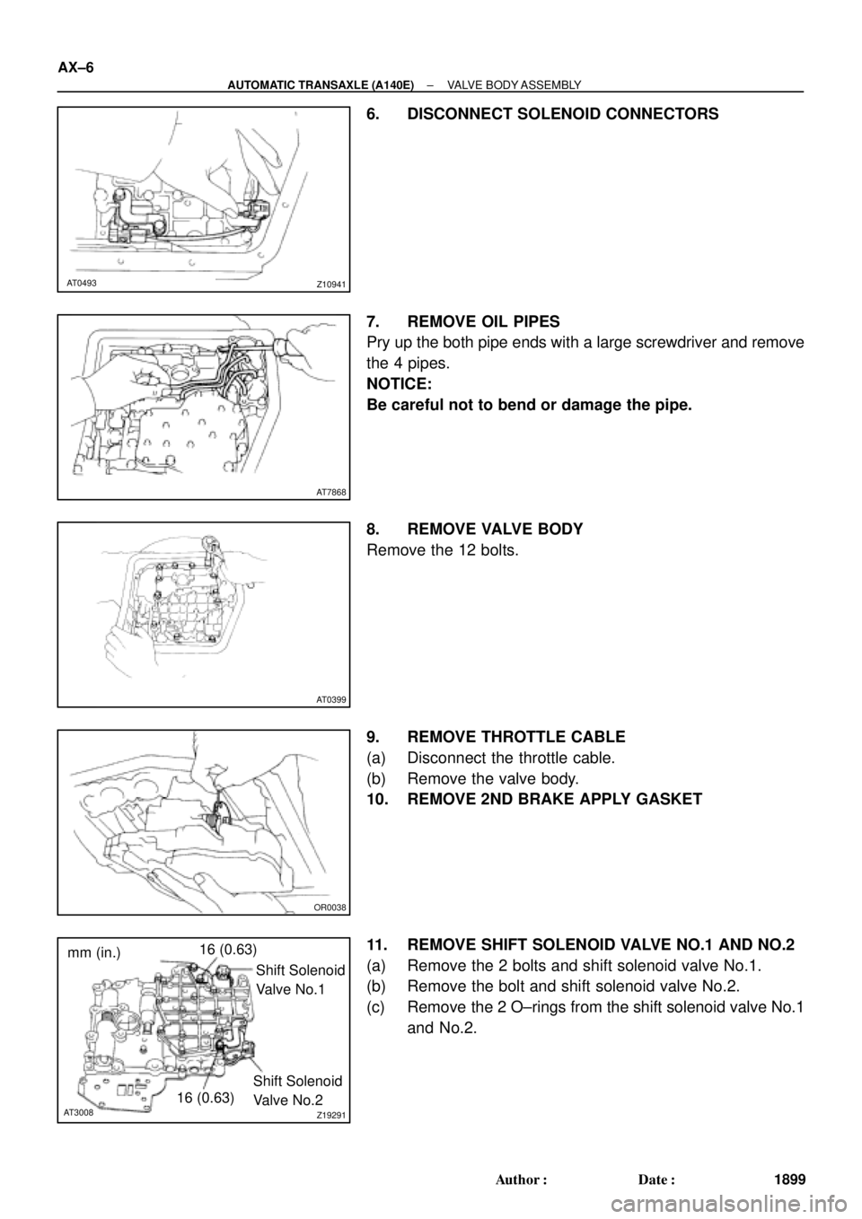
6. DISCONNECT SOLENOID CONNECTORS
7. REMOVE OIL PIPES
Pry up the both pipe ends with a large screwdriver and remove
the 4 pipes.
NOTICE:
Be careful not to bend or damage the pipe.
8. REMOVE VALVE BODY
Remove the 12 bolts.
9. REMOVE THROTTLE CABLE
(a) Disconnect the throttle cable.
(b) Remove the valve body.
10. REMOVE 2ND BRAKE APPLY GASKET
11. REMOVE SHIFT SOLENOID VALVE NO.1 AND NO.2
(a) Remove the 2 bolts and shift solenoid valve No.1.
(b) Remove the bolt and shift solenoid valve No.2.
(c) Remove the 2 O±rings from the shift solenoid valve No.1
and No.2.
Page 101 of 4592

OR0038
Z10942
C
DB
A
CBA B
AT0492
AT7870
Z10941 AT0493
Shift Solenoid Valve No.2
BlackWhite
Shift Solenoid Valve No.1
± AUTOMATIC TRANSAXLE (A140E)VALVE BODY ASSEMBLY
AX±7
1900 Author�: Date�:
12. INSTALL SHIFT SOLENOID VALVE NO.1 AND NO.2
(a) Coat 2 new O±rings with ATF.
(b) Install the 2 O±rings to the shift solenoid valve No.1 and
No.2.
(c) Install the shift valve No.1 with the 2 bolts.
Torque: 5.4 N´m (55 kgf´cm, 48 in.´lbf)
(d) Install the shift valve No.2 with the bolt.
Torque: 5.4 N´m (55 kgf´cm, 48 in.´lbf)
13. INSTALL NEW 2ND BRAKE APPLY GASKET
14. INSTALL VALVE BODY
(a) While holding the cam down by your hand, slip the cable
end into the slot.
NOTICE:
Do not entangle the solenoid wire.
(b) Install the valve body with the 12 bolts.
HINT:
Temporarily install the 12 bolts first, then tighten the 12 bolts.
Torque: 10 N´m (100 kgf´cm, 7 ft´lbf)
Bolt length:
Bolt A: 20 mm (0.79 in.)
Bolt B: 25 mm (0.98 in.)
Bolt C: 36 mm (1.42 in.)
Bolt D: 50 mm (1.97 in.)
15. INSTALL OIL PIPES
Using a plastic hammer, install the 4 pipes into the positions in-
dicated in the illustration.
NOTICE:
Be careful not to bend or damage the pipes.
16. CONNECT SOLENOID CONNECTORS
Connect the black wire harness to shift solenoid valve No.2 and
white wire harness to shift solenoid valve No.1.
Page 102 of 4592
Z10940
mm (in.)
20
(0.78)
45
(1.772)50
(1.969)
AT3336
Z10944
mm (in.)
36 (1.417)
14 (0.551)
AT2711
Z10945
Magnets
AT2368
Q00073
AX±8
± AUTOMATIC TRANSAXLE (A140E)VALVE BODY ASSEMBLY
1901 Author�: Date�:
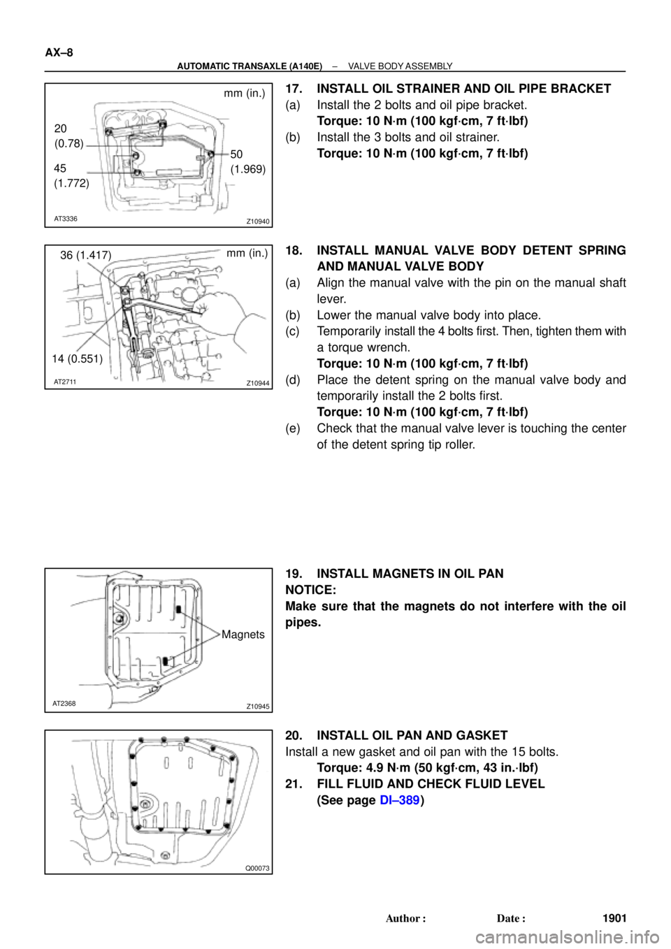
17. INSTALL OIL STRAINER AND OIL PIPE BRACKET
(a) Install the 2 bolts and oil pipe bracket.
Torque: 10 N´m (100 kgf´cm, 7 ft´lbf)
(b) Install the 3 bolts and oil strainer.
Torque: 10 N´m (100 kgf´cm, 7 ft´lbf)
18. INSTALL MANUAL VALVE BODY DETENT SPRING
AND MANUAL VALVE BODY
(a) Align the manual valve with the pin on the manual shaft
lever.
(b) Lower the manual valve body into place.
(c) Temporarily install the 4 bolts first. Then, tighten them with
a torque wrench.
Torque: 10 N´m (100 kgf´cm, 7 ft´lbf)
(d) Place the detent spring on the manual valve body and
temporarily install the 2 bolts first.
Torque: 10 N´m (100 kgf´cm, 7 ft´lbf)
(e) Check that the manual valve lever is touching the center
of the detent spring tip roller.
19. INSTALL MAGNETS IN OIL PAN
NOTICE:
Make sure that the magnets do not interfere with the oil
pipes.
20. INSTALL OIL PAN AND GASKET
Install a new gasket and oil pan with the 15 bolts.
Torque: 4.9 N´m (50 kgf´cm, 43 in.´lbf)
21. FILL FLUID AND CHECK FLUID LEVEL
(See page DI±389)