Page 3 of 4592

AC0LI±02
N20242
Sight Glass
± AIR CONDITIONINGAIR CONDITIONING SYSTEM
AC±3
2485 Author�: Date�:
ON±VEHICLE INSPECTION
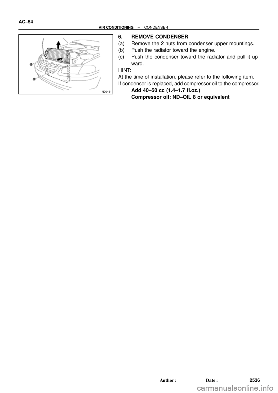
1. INSPECT REFRIGERANT VOLUME
Observe the sight glass on the liquid tube.
Test conditions:
�Running engine at 1,500 rpm
�Blower speed control switch at ºHIº position
�A/C switch ON
�Temperature control dial at ºCOOLº position
�Fully open the doors
ItemSymptomAmount of refrigerantRemedy
1Bubbles present in sight glassInsufficient*
(1) Check for gas leakage with gas leak de-
tector and repair if necessary
(2) Add refrigerant until bubbles disappear
2No bubbles present in sight glassNone, sufficient or too muchRefer item 3 and 4
3No temperature difference between com-
pressor inlet and outletEmpty or nearly empty
(1) Check for gas leakage with gas leak de-
tector and repair if necessary
(2) Add refrigerant until bubbles disappear
4Temperature between compressor inlet and
outlet is noticeably differentCorrect or too muchRefer to items 5 and 6
5Immediately after air conditioning is turned
off, refrigerant in sight glass stays clearToo much
(1) Discharge refrigerant
(2) Evacuate air and charge proper amount
or purified refrigerant
6When air conditioning is turned off, refriger-
ant foams and then stays clearCorrect±
*: Bubbles in the sight glass with ambient temperatures higher than usual can be considered normal if cooling
is sufficient.
Page 7 of 4592

I01390
Condition: Insufficient cooling
I01392
Condition: Insufficient cooling
NOTE : These gauge indica-
tions are shown when the
refrigeration system has
been opened and the refrig-
erant charged without vacu-
um purging.
± AIR CONDITIONINGAIR CONDITIONING SYSTEM
AC±7
2489 Author�: Date�:
(6) Refrigerant overcharged or insufficient cooling of
condenser
Symptom seen in
refrigeration systemProbable causeDiagnosisRemedy
� Pressure too high on both low
and high pressure sides
� No air bubbles seen through the
sight glass even when the engine
rpm is lowered� Unable to develop sufficient per-
formance due to excessive refrig-
eration system
� Insufficient cooling of condenser� Excessive refrigerant in
cycle " refrigerant over charged
� Condenser cooling " condenser
fins clogged of condenser fan
faulty
(1) Clean condenser
(2) Check condenser fan motor
operation
(3) If (1) and (2) are in normal
state, check amount of refrigerant
Charge proper amount of refriger-
ant
(7) Air present in refrigeration system
Symptom seen in
refrigeration systemProbable causeDiagnosisRemedy
� Pressure too high on both low
and high pressure sides
� The low pressure piping hot to
touch
� Bubbles seen in sight glass
Air entered in refrigeration system
� Air present in refrigeration sys-
tem
� Insufficient vacuum purging
(1) Check compressor oil to see if
it is dirty or insufficient
(2) Evacuate air and charge new
refrigerant
Page 12 of 4592

N13790
Low Pressure
Service Valve
High Pressure
Service Valve
I07055
Properly
Charged
Insufficiently
Charged AC±12
± AIR CONDITIONINGAIR CONDITIONING SYSTEM
2494 Author�: Date�:
3. CHARGE REFRIGERANT INTO REFRIGERANT SYS-
TEM
If there is no leak after refrigerant leak check, charge the proper
amount of refrigerant into refrigeration system.
CAUTION:
�Never run the engine when charging the system
through the high pressure side.
�Do not open the low pressure hand valve when the
system is being charged with liquid refrigerant.
(a) Open the high pressure hand valve fully.
(b) Charge specified amount of refrigerant, then close the
high pressure hand valve.
HINT:
A fully charged system is indicated by the sight glass being free
of any bubbles.
(c) Charge partially refrigeration system with refrigerant.
(1) Set vehicle in these conditions:
�Running engine at 1,500 rpm
�Blower speed control set at ºHIº
�Temperature control set at ºMAX. COOLº
�Air inlet control set at ºRECIRCº
�Fully open doors (Sliding roof: closed)
(2) Open the low pressure hand valve.
CAUTION:
Do not open the high pressure hand valve.
(d) Charge refrigerant until bubbles disappear and check the
pressure on the gauge through the sight glass.
Page 27 of 4592
AC21W±01
N20288
N20237
Water Hose
MarkingUpper
LH
Hose ClipRH Heater Radiator Pipe
45 ± 10°
Lower
I09160
± AIR CONDITIONINGAIR CONDITIONING UNIT
AC±27
2509 Author�: Date�:
REMOVAL
1. DISCHARGE REFRIGERANT FROM REFRIGERATION
SYSTEM
HINT:
At the time of installation, please refer to the following item.
Evacuate air from refrigeration system.
Charge system with refrigerant and inspect for leakage of refrig-
erant.
Specified amount: 800 ± 50 g (28.22 ± 1.76 oz.)
2. DRAIN ENGINE COOLANT FROM RADIATOR
HINT:
It is not necessary to drain out all the coolant.
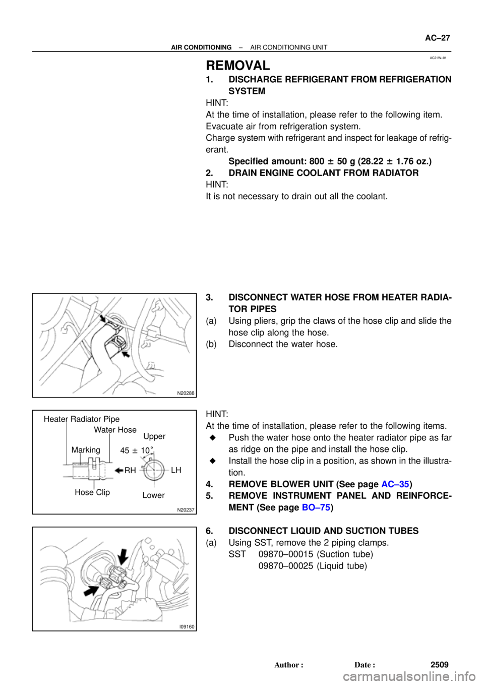
3. DISCONNECT WATER HOSE FROM HEATER RADIA-
TOR PIPES
(a) Using pliers, grip the claws of the hose clip and slide the
hose clip along the hose.
(b) Disconnect the water hose.
HINT:
At the time of installation, please refer to the following items.
�Push the water hose onto the heater radiator pipe as far
as ridge on the pipe and install the hose clip.
�Install the hose clip in a position, as shown in the illustra-
tion.
4. REMOVE BLOWER UNIT (See page AC±35)
5. REMOVE INSTRUMENT PANEL AND REINFORCE-
MENT (See page BO±75)
6. DISCONNECT LIQUID AND SUCTION TUBES
(a) Using SST, remove the 2 piping clamps.
SST 09870±00015 (Suction tube)
09870±00025 (Liquid tube)
Page 48 of 4592
AC0M9±02
N20259
(A)
(B)
± AIR CONDITIONINGCOMPRESSOR AND MAGNETIC CLUTCH
AC±47
2529 Author�: Date�:
INSTALLATION
1. 5S±FE engine models:
INSTALL COMPRESSOR
(a) Install the compressor with 3 bolts.
Torque: 25 N´m (250 kgf´cm, 18 ft´lbf)
(b) Connect the connector.
2. 1MZ±FE engine models:
INSTALL COMPRESSOR
(a) Install the compressor with 3 bolts.
Torque: 25 N´m (250 kgf´cm, 18 ft´lbf)
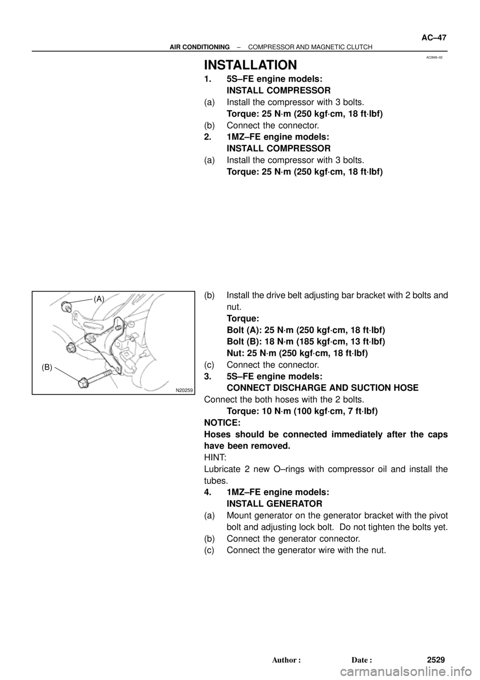
(b) Install the drive belt adjusting bar bracket with 2 bolts and
nut.
Torque:
Bolt (A): 25 N´m (250 kgf´cm, 18 ft´lbf)
Bolt (B): 18 N´m (185 kgf´cm, 13 ft´lbf)
Nut: 25 N´m (250 kgf´cm, 18 ft´lbf)
(c) Connect the connector.
3. 5S±FE engine models:
CONNECT DISCHARGE AND SUCTION HOSE
Connect the both hoses with the 2 bolts.
Torque: 10 N´m (100 kgf´cm, 7 ft´lbf)
NOTICE:
Hoses should be connected immediately after the caps
have been removed.
HINT:
Lubricate 2 new O±rings with compressor oil and install the
tubes.
4. 1MZ±FE engine models:
INSTALL GENERATOR
(a) Mount generator on the generator bracket with the pivot
bolt and adjusting lock bolt. Do not tighten the bolts yet.
(b) Connect the generator connector.
(c) Connect the generator wire with the nut.
Page 49 of 4592
AC±48
± AIR CONDITIONINGCOMPRESSOR AND MAGNETIC CLUTCH
2530 Author�: Date�:
5. 1MZ±FE engine models:
CONNECT DISCHARGE HOSE
Connect the discharge hose with the bolt.
Torque: 10 N´m (100 kgf´cm, 7 ft´lbf)
NOTICE:
Hoses should be connected immediately after the caps
have been removed.
HINT:
Lubricate a new O±ring with compressor oil and install the tube.
6. INSTALL SUCTION HOSE
(a) Install the suction hose and tighten the bolt and nut.
Torque:
Piping joint: 32 N´m (330 kgf´cm, 24 ft´lbf)
Block joint: 10 N´m (100 kgf´cm, 7 ft´lbf)
HINT:
Lubricate 2 new O±rings with compressor oil and install the
hose.
(b) Install the suction hose clamping bolt.
(c) Connect the wire harness clamp.
7. INSTALL AND CHECK DRIVE BELT
(See page AC±18, AC±16)
8. CONNECT NEGATIVE (±) TERMINAL CABLE TO BAT-
TERY
9. EVACUATE AIR FROM REFRIGERATION SYSTEM
AND CHARGE SYSTEM WITH REFRIGERANT
Specified amount: 800 ± 50 g (28.22 ± 1.76 oz.)
10. INSPECT FOR LEAKAGE OF REFRIGERANT
Using a gas leak detector, check for leakage of refrigerant.
If there is leakage, check the tightening torque at the joints.
11. INSPECT A/C OPERATION
Page 55 of 4592
N20451
AC±54
± AIR CONDITIONINGCONDENSER
2536 Author�: Date�:
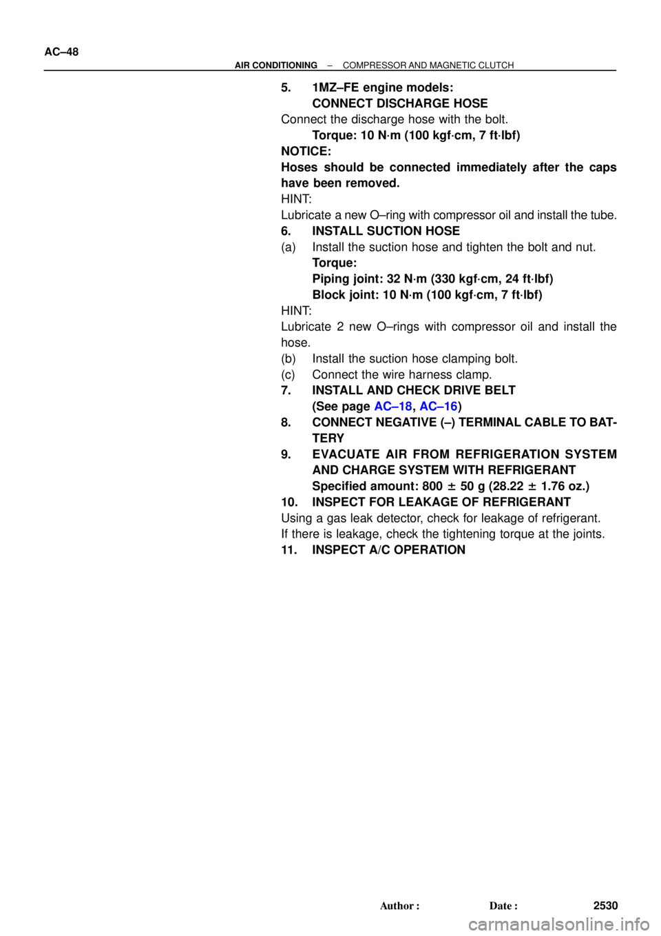
6. REMOVE CONDENSER
(a) Remove the 2 nuts from condenser upper mountings.
(b) Push the radiator toward the engine.
(c) Push the condenser toward the radiator and pull it up-
ward.
HINT:
At the time of installation, please refer to the following item.
If condenser is replaced, add compressor oil to the compressor.
Add 40±50 cc (1.4±1.7 fl.oz.)
Compressor oil: ND±OIL 8 or equivalent
Page 112 of 4592
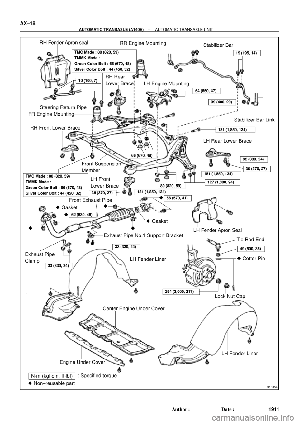
Q10054
RH Fender Apron seal
RR Engine Mounting
Stabilizer Bar
10 (100, 7)RH Rear
Lower Brace
Steering Return Pipe
19 (195, 14)
FR Engine Mounting
Stabilizer Bar Link
Front Suspension
Member
�
Front Exhaust Pipe
RH Front Lower Brace
LH Engine Mounting
66 (670, 48)
64 (650, 47)
39 (400, 29)
181 (1,850, 134)
LH Rear Lower Brace
32 (330, 24)
36 (370, 27)
181 (1,850, 134)
127 (1,300, 94)80 (820, 59)
TMC Made : 80 (820, 59)
TMMK Made :
Green Color Bolt : 66 (670, 48)
Silver Color Bolt : 44 (450, 32)
TMC Made : 80 (820, 59)
TMMK Made :
Green Color Bolt : 66 (670, 48)
Silver Color Bolt : 44 (450, 32)LH Front
Lower Brace
36 (370, 27)181 (1,850, 134)
56 (570, 41)
�
�� � Gasket
62 (630, 46)
Tie Rod End
Lock Nut Cap
Engine Under CoverLH Fender Liner � Gasket
�
Exhaust Pipe No.1 Support Bracket
33 (330, 24)
33 (330, 24)
Exhaust Pipe
ClampLH Fender Liner
LH Fender Apron Seal
� Cotter Pin
49 (500, 36)
294 (3,000, 217)
Center Engine Under Cover
N´m (kgf´cm, ft´lbf): Specified torque
� Non±reusable part AX±18
± AUTOMATIC TRANSAXLE (A140E)AUTOMATIC TRANSAXLE UNIT
1911 Author�: Date�: