Page 1345 of 4592
± DIAGNOSTICSENGINE (5S±FE)
DI±133
368 Author�: Date�:
7 Check vacuum hose between intake manifold and VSV for EVAP, and VSV for
EVAP and charcoal canister.
CHECK:
(a) Check that the vacuum hose is connected correctly.
(b) Check the vacuum hose for looseness and disconnection.
(c) Check the vacuum hose for cracks, hole, damage and blockage.
NG Repair or replace.
OK
8 Check operation of VSV for EVAP (See page SF±45).
OK Go to step 9.
NG
Replace VSV, charcoal canister and then clean the vacuum hose between throttle body and VSV
for EVAP, and VSV for EVAP and charcoal canister.
9 Check for open and short in harness and connector between EFI main relay
(Marking: EFI) and VSV for EVAP, and VSV for EVAP and ECM
(See page IN±31).
NG Repair or replace harness or connector.
OK
Check and replace ECM (See page IN±31).
Page 1347 of 4592

E2 (±)
E2 (±) w/o Immobiliser
w/ Immobiliser
PTNK (+)
Vapor Pressure Sensor
± DIAGNOSTICSENGINE (5S±FE)
DI±135
370 Author�: Date�:
12 Check for ope")
A03018
A03280
A03421
VSV Connector for
PTNK (+)
E2 (±)
E2 (±) w/o Immobiliser
w/ Immobiliser
PTNK (+)
Vapor Pressure Sensor
± DIAGNOSTICSENGINE (5S±FE)
DI±135
370 Author�: Date�:
12 Check for open and short in harness and connector between EFI main relay
(Marking: EFI) and VSV for vapor pressure sensor, and VSV for vapor pressure
sensor and ECM (See page IN±31).
NG Repair or replace harness or connector.
OK
Check and replace ECM (See page IN±31).
13 When VSV connector for vapor pressure sensor is disconnected and VSV for
EVAP is ON, measure voltage between terminals PTNK and E2 of ECM connector.
PREPARATION:
(a) Remove the glove compartment (See page SF±64).
(b) Connect the TOYOTA hand±held tester to the DLC3.
(c) Disconnect the VSV connector for the vapor pressure
sensor.
(d) Select the ACTIVE TEST mode on the TOYOTA hand±
held tester.
(e) Start the engine.
CHECK:
Measure voltage between terminals PTNK and E2 of the ECM
connector using the TOYOTA hand±held tester when the VSV
for the EVAP is ON.
OK:
Voltage: 2.0 V or less
OK Go to step 15.
NG
Page 1352 of 4592
A03020A03424
ON
OFF
ONTPC
E
G
FFE
G
VSV is ON
VSV is OFF OFFONTPC
w/o Immobiliser
w/ Immobiliser
DI±140
± DIAGNOSTICSENGINE (5S±FE)
375 Author�: Date�:
8 Check for open and short in harness and connector between EFI main relay
(Marking: EFI) and VSV for EVAP, and VSV for EVAP and ECM (See page IN±31)
NG Repair or replace harness or connector.
OK
Check and replace ECM (See page IN±31).
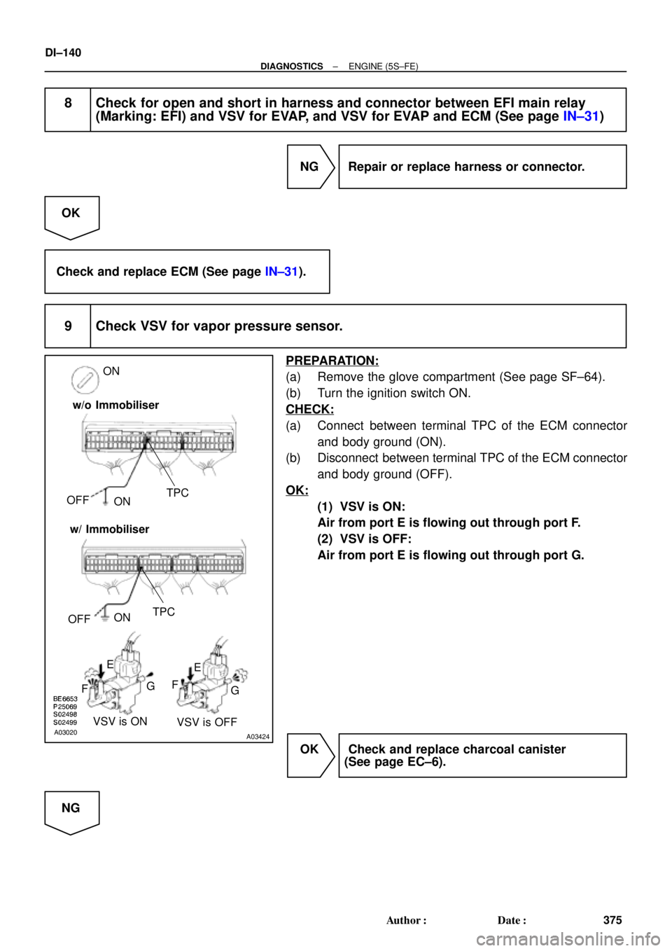
9 Check VSV for vapor pressure sensor.
PREPARATION:
(a) Remove the glove compartment (See page SF±64).
(b) Turn the ignition switch ON.
CHECK:
(a) Connect between terminal TPC of the ECM connector
and body ground (ON).
(b) Disconnect between terminal TPC of the ECM connector
and body ground (OFF).
OK:
(1) VSV is ON:
Air from port E is flowing out through port F.
(2) VSV is OFF:
Air from port E is flowing out through port G.
OK Check and replace charcoal canister
(See page EC±6).
NG
Page 1353 of 4592
± DIAGNOSTICSENGINE (5S±FE)
DI±141
376 Author�: Date�:
10 Check operation of VSV for vapor pressure sensor (See page SF±47).
NG Go to step 11.
OK
Replace VSV and clean vacuum hoses between charcoal canister and VSV for vapor pressure
sensor, and VSV for vapor pressure sensor and vapor pressure sensor, and then check the char-
coal canister.
11 Check for open and short in harness and connector between EFI main relay
(Marking: EFI) and VSV for vapor pressure sensor, and VSV for vapor pressure
sensor and ECM (See page IN±31).
NG Repair or replace harness or connector.
OK
Check and replace ECM (See page IN±31).
12 Check fuel tank over fill check valve (See page EC±6).
NG Replace fuel tank over fill check valve or fuel
tank.
OK
Check and replace charcoal canister
(See page EC±6).
Page 1360 of 4592

P01559
Throttle Valve
To Cylinder ECM Signal From
Air
Cleaner
Valve
IAC Valve
Intake Air
Chamber
A07553
B±Y 9
2B±Y B±Y
II3J19
J/CIAC ValveECM
1
3 2
B
EFI
5
1 Engine Room J/B No.2
42
2J
W±B
B
ISCO
E01
E01 ISCC10
9W
B±OE9
E9
1
2A
2K
EFI Relay
EB
From
BatteryB
*1: w/o Immobiliser
*2: w/ Immobiliser(*1) (*2)
E97
E96
(*2) (*1)
E107MREL2FB±W B±W
II4
(*2)
7
6(*2) (*2)
3
B±R
(*1)From
Ignition SW DI±148
± DIAGNOSTICSENGINE (5S±FE)
383 Author�: Date�:
DTC P0505 Idle Control System Malfunction
CIRCUIT DESCRIPTION
The rotary solenoid type IAC valve is located on the throttle
body and intake air bypassing the throttle valve is directed to
the IAC valve through a passage.
In this way the intake air volume bypassing the throttle valve is
regulated, controlling the engine speed.
The ECM operates only the IAC valve to perform idle±up and
provide feedback for the target idling speed.
DTC No.DTC Detecting ConditionTrouble AreaTrouble Area
P0505Idle speed continues to vary greatly from the target speed
(2 trip detection logic)
�IAC valve is stuck or closed
�Open or short in IAC valve circuit
�Open or short in A/C switch circuit
�Air intake (hose loose)
�ECM
WIRING DIAGRAM
DI01C±05
Page 1374 of 4592
DI±162
± DIAGNOSTICSENGINE (5S±FE)
397 Author�: Date�:
2 Check resistance of A/F sensor heater (See page SF±59).
NG Replace A/F sensor.
OK
Check and repair harness or connector between EFI main relay (Marking: EFI) and A/F sensor,
and A/F sensor and ECM (See page IN±31).
Page 1380 of 4592
DI±168
± DIAGNOSTICSENGINE (5S±FE)
403 Author�: Date�:
8 Check for open and short in harness and connector between ignition switch and
ignition coils (See page IN±31).
NG Repair or replace harness or connector.
OK
9 Check ignition coil (See page IG±5).
NG Replace ignition coil.
OK
10 Check EFI main relay (Marking: EFI) (See page SF±40).
NG Replace EFI main relay.
OK
Replace igniter.
Page 1387 of 4592

DI±175
410 Author�: Date�:
DTC P1780 Park/Neutral Position Switch Malfunction
(Only for A/T)
CIRCUIT DESCRIPTION
The park/neutral position switch goes on when the shift")
± DIAGNOSTICSENGINE (5S±FE)
DI±175
410 Author�: Date�:
DTC P1780 Park/Neutral Position Switch Malfunction
(Only for A/T)
CIRCUIT DESCRIPTION
The park/neutral position switch goes on when the shift lever is in the N or P shift position. When it goes on
terminal NSW of the ECM is grounded to body ground via the starter relay thus the terminal NSW voltage
becomes 0V. When the shift lever is in the D, 2, L or R position, the park/neutral position switch goes off,
so the voltage of ECM. Terminal NSW becomes battery positive voltage, the voltage of the ECM internal
power source.
If the shift lever is moved from the N position to the D position, this signal is used for air±fuel ratio correction
and for idle speed control (estimated control), etc.
DTC No.DTC Detecting ConditionTrouble Area
2 or more switches are ON simultaneously for P, R, N, D, 2
and L positions
(2 trip detection logic)
Sh t i k/ t l iti it h i it
P1780When driving under conditions (a) and (b) for 30 sec. or more
park/neutral position switch is ON (N position):
(2 trip detection logic)
(a) Vehicle speed: 80 km/h (50 mph) or more
(b) Engine speed: 2,000 ~ 5,000 rpm�Short in park/neutral position switch circuit
�Park/neutral position switch
�ECM
HINT:
After confirming DTC P1780, use the TOYOTA hand±held tester to confirm the PNP switch signal from the
CURRENT DATA.
WIRING DIAGRAM
Refer to DTC P1780 on page DI±424.
INSPECTION PROCEDURE
HINT:
Read freeze frame data using TOYOTA hand±held tester or OBD II scan tool. Because freeze frame records
the engine conditions when the malfunction is detected, when troubleshooting it is useful for determining
whether the vehicle was running or stopped, the engine warmed up or not, the air±fuel ratio lean or rich, etc.
at the time of the malfunction.
Refer to DTC P1780 on DI±424.
DI01J±05