Page 790 of 4592

BE0AS±02
N21643
Wire harness side:
12 3
4567 8
s±8±1
BE±74
± BODY ELECTRICALSLIDING ROOF SYSTEM
2294 Author�: Date�:
INSPECTION
1. INSPECT SLIDING ROOF CONTROL RELAY AND
SWITCH CIRCUIT
Disconnect the connector from the relay and switch and inspect
the connector on the wire harness side, as shown in the table.
TMMK made:
Tester connectionConditionSpecified condition
1 ± 5ConstantContinuity
2 ± GroundConstantContinuity
3 ± GroundLimit switch No.1 is OFF (Sliding roof is in a
closed position)No continuity
3 ± GroundLimit switch No.1 is ON (Sliding roof is in an open
position)Continuity
7 ± GroundLimit switch No.2 is OFF (Sliding roof is in a tilt
up position)No continuity
7 ± GroundLimit switch No.2 is ON (Sliding roof is in the
open position)Continuity
8 ± GroundLimit switch No.3 is OFF (Sliding roof is in a
closed position)No continuity
8 ± GroundLimit switch No.3 is ON (Sliding roof is in an open
position)Continuity
4 ± GroundIgnition switch is in a LOCK or ACC position* No voltage
4 ± GroundIgnition switch is in an ON positionBattery positive voltage
TMC made:
Tester connectionConditionSpecified condition
1 ± 5ConstantContinuity
2 ± GroundConstantContinuity
3 ± GroundNo.1 limit switch OFF (Sliding roof closed)No continuity
3 ± GroundNo.1 limit switch ON (Sliding roof opened)Continuity
7 ± GroundNo.2 limit switch OFF (Sliding roof tilted up open
approx. 200 mm (7.87 in.)No continuity
7 ± GroundNo.2 limit switch ON (Except for conditions
mentioned above)Continuity
4 ± GroundIgnition switch LOCK or ACC* No voltage
4 ± GroundIgnition switch ONBattery positive voltage
*: Exceptions: For 60 seconds after the ignition switch is turned
ON to OFF (ACC) or until driver or passenger door is opened
after the ignition switch is turned ON to OFF (ACC).
If the circuit is not as specified, replace the relay and switch.
Page 792 of 4592

N21645
within 60
seconds
N21872
No.3
Limit Switch
No.1
Limit Switch
No.2
Limit Switch ON
OFF
N21180
No.1
Limit Switch
No.2
Limit Switch ON
OFF1
2
3 4
5
6 BE±76
± BODY ELECTRICALSLIDING ROOF SYSTEM
2296 Author�: Date�:
(b) With the sliding roof in fully opened position, hold the slid-
ing roof switch in ºTILT UPº position and check that the
sliding roof begins to close within 60 seconds.
If operation is not as specified, replace the motor.
4. TMMK made:
INSPECT SLIDING ROOF LIMIT SWITCH CIRCUIT
Switch positionTester connectionSpecified condition
No.1 limit switch OFF
(SW pin released)3 ± 5No continuity
No.1 limit switch ON
(SW pin pushed in)3 ± 5Continuity
No.2 limit switch OFF
(SW pin released)3 ± 6No continuity
No.2 limit switch ON
(SW pin pushed in)3 ± 6Continuity
No.3 limit switch OFF
(SW pin released)3 ± 4No continuity
No.3 limit switch ON
(SW pin pushed in)3 ± 4Continuity
5. TMC made:
INSPECT SLIDING ROOF LIMIT SWITCH CIRCUIT
Switch positionTester connectionSpecified condition
No.1 limit switch OFF
(SW pin released)4 ± 5No continuity
No.1 limit switch ON
(SW pin pushed in)4 ± 5Continuity
No.2 limit switch OFF
(SW pin released)4 ± 6No continuity
No.2 limit switch ON
(SW pin pushed in)4 ± 6Continuity
If continuity is not as specified, replace the switch.
6. INSPECT KEY±OFF SLIDING ROOF OPERATION
(See integration relay circuit on page BE±14)
Page 981 of 4592
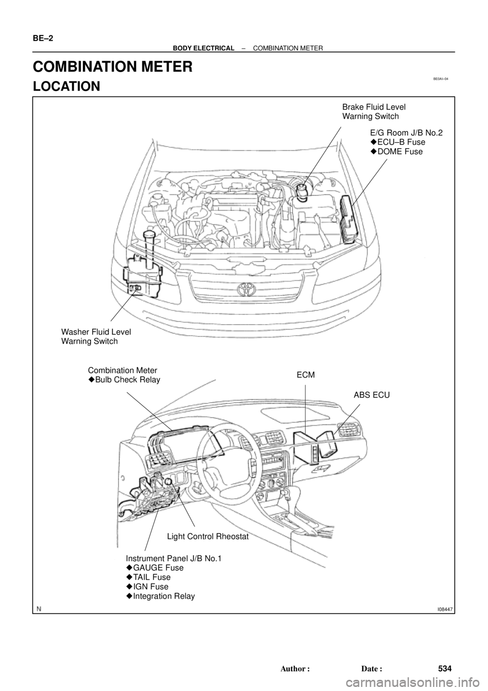
BE0AI±04
I08447
Brake Fluid Level
Warning Switch
E/G Room J/B No.2
� ECU±B Fuse
� DOME Fuse
Washer Fluid Level
Warning Switch
Combination Meter
� Bulb Check RelayECM
ABS ECU
Light Control Rheostat
Instrument Panel J/B No.1
� GAUGE Fuse
� TAIL Fuse
� IGN Fuse
� Integration Relay
BE±2
± BODY ELECTRICALCOMBINATION METER
534 Author�: Date�:
COMBINATION METER
LOCATION
Page 983 of 4592

BE0AJ±04
Z18937
Connector ºAº Connector ºBº Connector ºCº
Connector ºAº
Connector ºBº
Connector ºCº
J±13±1±A J±16±1 J±13±1
1 2 3 4 5 6 7 8 9 10 11 12 1314 15 16 1 234 56 78 910111213 1 23456 78910111213
C7
C5
A2 B3
A1
C8
B15
C6
B6
A4
C4
B5
C10 B14
A13
B2
C1
B1
C9
A6
A11
A7
A10
A8
A9
C13
B8
B11
B12A5
C11
B4
B16 C2
A12
A3
B7
C3
C12
B9
B10
B13 F
E
T
S
ODOMETER
Fuel Level Warning
Seat Belt Warning
ABS Warning
Low Oil Pressure Warning
Cruise Control Indicator
Malfunction Indicator
O/D OFF Indicator
Light Failure Warning
Brake Warning
SLIP Indicator
TRAC Indicator
Washer Level Warning
Discharge Warning
Right Turn Indicator
Left Turn Indicator
Security Indicator
L
2
D
N
R
P
Illumination
Hi±Beam Indicator
Open Door Warning
SRS Warning
: Fuel Gauge
: Engine Coolant Temperature Sender Gauge
: Tachometer
: Speedometer
No.
A
B
C1
2
3
4
5
6
7 8
9
10
11
12 13
14
15
16
2 3
4
5
6
7 8
9
10
11 12
131
2
3
4 5
6
7
8
9
10
11
12
13
F
E
T
SEngine coolant temperature sender gauge
Ground
Light failure sensor
Integration relay
Traction ECU
Park/neutral position switch (A/T)
O/D OFF switch (A/T)
IGN fuse
Turn signal switch
ST relay
ECM
Generator
Oil pressure switch
ECM
Parking brake switch and brake fluid level warning switch
Headlight dimmer switch
Headlight dimmer switch
Door courtesy switch
DOME fuse
ECU±B fuse
Airbag sensor assembly
ECM
No.1 Vehicle speed sensor Ground
Turn signal switch ECM
Traction ECU
ABS ECU
Ground No.1 Vehicle speed sensor
GAUGE fuse
Igniter
Security ECU
Cruise control ECU
Washer fluid level warning switch
Light control rheostat
TAIL fuse Park/neutral position switch (A/T) Park/neutral position switch (A/T) Park/neutral position switch (A/T) Park/neutral position switch (A/T)
Park/neutral position switch (A/T)Wire Harness Side
Bulb Check
Relay
N20107 N201081
BE±4
± BODY ELECTRICALCOMBINATION METER
CIRCUIT
Page 1064 of 4592
 Sub±Wire Harness G (SST)
ABSSub±Wire Harness L (SST)
Sub±Wire Harness I (SST) ActuatorABS Actuator Checker BR±50
± BRAKEABS ACTUATOR (DENSO Made)
2073 Author�: Date�")
BR0BD±02
W03244
R09422
(SST) Sub±Wire Harness G (SST)
ABSSub±Wire Harness L (SST)
Sub±Wire Harness I (SST) ActuatorABS Actuator Checker BR±50
± BRAKEABS ACTUATOR (DENSO Made)
2073 Author�: Date�:
ABS ACTUATOR (DENSO Made)
ON±VEHICLE INSPECTION
HINT:
Using the ABS actuator checker (SST), check the operation of
the actuator. If the actuator does not operate, check the opera-
tion of sub±wire harness G according to the instructions on
pages DI±502 and DI±507. If the solenoid and/or pump motor
relay are abnormal, replace the relay and inspect the actuator
operation again.
1. INSPECT BATTERY POSITIVE VOLTAGE
Battery positive voltage: 10 ± 14 V
2. DISCONNECT CONNECTORS
Disconnect the 2 connectors from the actuator.
3. CONNECT ACTUATOR CHECKER (SST)
(a) Connect the actuator checker (SST) to the actuator side
wire harness via the sub±wire harness (SST), as shown.
SST 09990±00150, 09990±00250, 09990±00300,
09990±00360
(b) Connect the red cable of the checker to the battery posi-
tive (+) terminal and black cable to the negative (±) termi-
nal. Connect the black cable of the sub±wire harness to
the battery negative (±) terminal or body ground.
Page 1075 of 4592

FR TRC
Connector
White
Connector
Sub ± Wire harness P (SST)
*: Connect the white connector with
the labeled (FF TRC) connector.(SST)
FF TRC
Con")
BR07A±06
W03246
W03897
Sub ± Wire Harness G (SST)
FR TRC
Connector
White
Connector
Sub ± Wire harness P (SST)
*: Connect the white connector with
the labeled (FF TRC) connector.(SST)
FF TRC
Connector Sub ± Wire
harness L
(SST)
ABS & TRAC
ActuatorABS Actuator Checker
± BRAKEABS & TRAC ACTUATOR
BR±61
2084 Author�: Date�:
ABS & TRAC ACTUATOR
ON±VEHICLE INSPECTION
HINT:
Using the ABS actuator checker (SST), check the operation of
the actuator. If the actuator does not operate, check the opera-
tion of sub±wire harness G according to the instructions on
pages DI±584 and DI±587. If the solenoid and/or pump motor
relay are abnormal, replace the relay and inspect the actuator
operation again.
1. INSPECT BATTERY POSITIVE VOLTAGE
Battery positive voltage: 10 ± 14 V
2. DISCONNECT CONNECTORS
Disconnect the 2 connectors from the actuator.
3. CONNECT ABS ACTUATOR CHECKER (SST)
(a) Connect the actuator checker (SST) to the actuator side
wire harness via the sub±wire harness (SST), as shown.
SST 09990±00150, 09990±00250, 09990±00360,
09990±00450
(b) Connect the red cable of the checker to the battery posi-
tive (+) terminal and black cable to the negative (±) termi-
nal. Connect the black cable of the sub±wire harness to
the battery negative (±) terminal or body ground.
Page 1164 of 4592

(+) (+)
(±)
Battery Ammeter CO±24
± COOLING (5S±FE)ELECTRIC COOLING FAN
1598 Author�: Date�:
ELECTRIC COOLING FAN")
S05959
CO06N±03
S05953
ECT Switch
Connector
Z19282
No.1
No.2Battery
Ammeter (±)
(+) (+)
(±)
Battery Ammeter CO±24
± COOLING (5S±FE)ELECTRIC COOLING FAN
1598 Author�: Date�:
ELECTRIC COOLING FAN
ON±VEHICLE INSPECTION
1. CHECK COOLING FAN OPERATION WITH LOW TEM-
PERATURE (Below 83°C (181°F))
(a) Turn the ignition switch ON.
(b) Check that the cooling fan stops.
If not, check the cooling fan relay and ECT switch, and check
for a separated connector or severed wire between the cooling
fan relay and ECT switch.
(c) Disconnect the ECT switch connector.
(d) Check that the cooling fan rotates.
If not, check the fan main relay, cooling fan relay, cooling fan,
fuses, and check for short circuit between the cooling fan relay
and ECT switch.
(e) Reconnect the ECT switch connector.
2. CHECK COOLING FAN OPERATION WITH HIGH TEM-
PERATURE (Above 93°C (199°F))
(a) Start the engine, and raise coolant temperature to above
93°C (199°F).
(b) Check that the cooling fan rotates.
If not, replace the ECT switch.
3. INSPECT COOLING FANS
(a) Disconnect the cooling fan connector.
(b) Connect battery and ammeter to the connector.
(c) Check that the cooling fan rotates smoothly, and check
the reading on the ammeter.
Standard amperage: 4.9 ± 8.5 A
(d) Reconnect the cooling fan connector.
Page 1172 of 4592

S05391
Engine
Main Relay
CO06U±03
B02803
Ohmmeter
Continuity
OhmmeterOhmmeter
No Continuity
Continuity21
5
43
B02804
Ohmmeter
Ohmmeter
No Continuity
Continuity 2
1
5
43
Battery
CO±32
± COOLING (5S±FE)ENGINE MAIN RELAY
1606 Author�: Date�:
ENGINE MAIN RELAY
INSPECTION
1. REMOVE RELAY BOX COVER
2. REMOVE ENGINE MAIN RELAY (Marking: ENGINE
MAIN)
3. INSPECT ENGINE MAIN RELAY
(a) Inspect the relay continuity.
(1) Using an ohmmeter, check that there is continuity
between terminals 3 and 5.
If there is no continuity, replace the relay.
(2) Check that there is continuity between terminals 2
and 4.
If there is no continuity, replace the relay.
(3) Check that there is no continuity between terminals
1 and 2.
If there is continuity, replace the relay.
(b) Inspect the relay operation.
(1) Apply battery positive voltage across terminals 3
and 5.
(2) Using an ohmmeter, check that there is no continu-
ity between terminals 2 and 4.
If there is continuity, replace the relay.
(3) Check that there is continuity between terminals 1
and 2.
If there is no continuity, replace the relay.
4. REINSTALL ENGINE MAIN RELAY
5. REINSTALL RELAY BOX COVER