Page 1388 of 4592

GR B±W (A/T)
B±WB±O (A/T,*2)
GR (A/T,*1) B±W
J/C J")
A03606
ECM
STA 11
E1 E7 Instrument
Panel J/BPark/Neutral
Position Switch
Clutch Start
SwitchB
J7
J7
B J8CJ/C II2 10 11
II26
2
B±O
5
1 B±W (M/T)
GR B±W (A/T)
B±WB±O (A/T,*2)
GR (A/T,*1) B±W
J/C J29
B B
B 3
1J 4
1K
5
1B 1K5
STARTER
R
8
7
W±R
IG SwitchW±R
Engine Room
J/B No. 2B
B FL
Block
B±G
B±R
BatteryStarter 11
W±B
A
J11
J/C
IG
42L
1
2A
3
2B
AM2
MAINST
Relay11 2 J
92K 52D 1 1
F6 F41 5
2 3
B±O (*2)
S2B±R MAIN
FL
GR (*1)(A/T)
S1
*1: TMC Made
*2: TMMK Made
GR (*1)
(*2)
(M/T)
B±O (*2) GR (*1)
DI±176
± DIAGNOSTICSENGINE (5S±FE)
411 Author�: Date�:
Starter Signal Circuit
CIRCUIT DESCRIPTION
When the engine is cranked, the intake air flow is slow, so fuel vaporization is poor. A rich mixture is therefore
necessary in order to achieve good startability. While the engine is being cranked, the battery positive volt-
age is applied to terminal STA of the ECM. The starter signal is mainly used to increase the fuel injection
volume for the starting injection control and after±start injection control.
WIRING DIAGRAM
DI01K±10
Page 1389 of 4592
± DIAGNOSTICSENGINE (5S±FE)
DI±177
412 Author�: Date�:
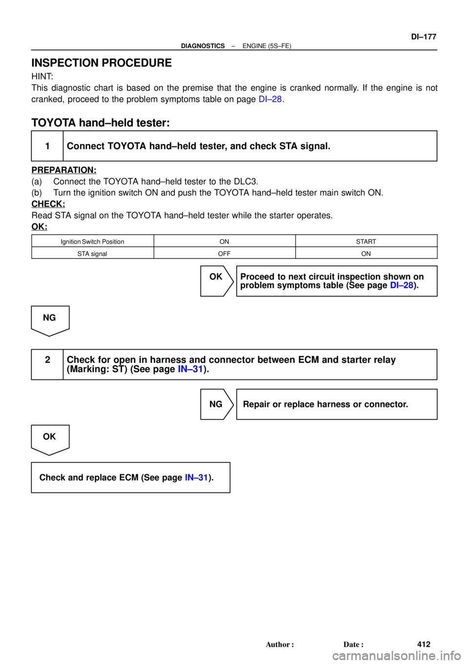
INSPECTION PROCEDURE
HINT:
This diagnostic chart is based on the premise that the engine is cranked normally. If the engine is not
cranked, proceed to the problem symptoms table on page DI±28.
TOYOTA hand±held tester:
1 Connect TOYOTA hand±held tester, and check STA signal.
PREPARATION:
(a) Connect the TOYOTA hand±held tester to the DLC3.
(b) Turn the ignition switch ON and push the TOYOTA hand±held tester main switch ON.
CHECK:
Read STA signal on the TOYOTA hand±held tester while the starter operates.
OK:
Ignition Switch PositionONSTART
STA signalOFFON
OK Proceed to next circuit inspection shown on
problem symptoms table (See page DI±28).
NG
2 Check for open in harness and connector between ECM and starter relay
(Marking: ST) (See page IN±31).
NG Repair or replace harness or connector.
OK
Check and replace ECM (See page IN±31).
Page 1390 of 4592
A03027A03449
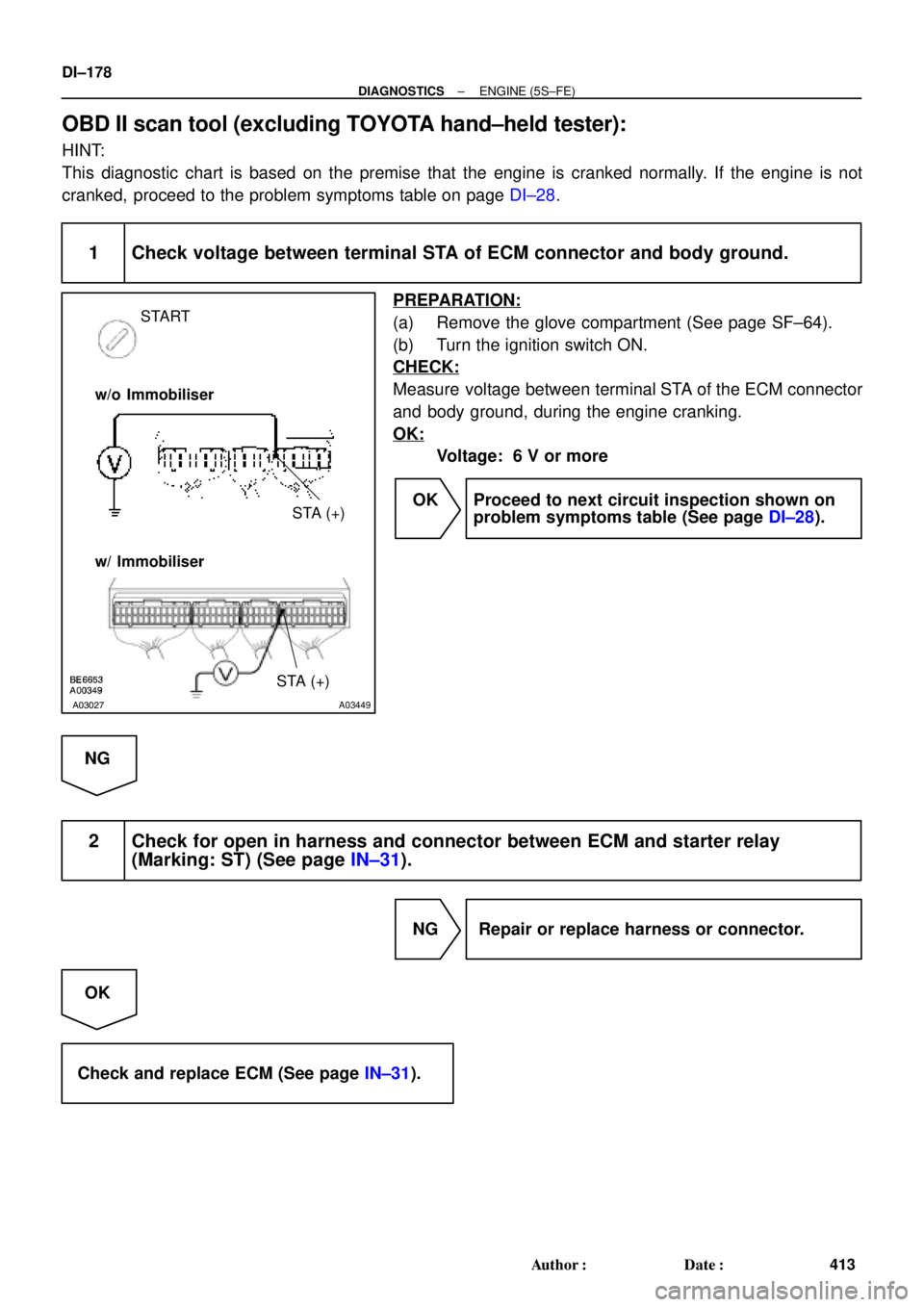
START
STA (+) w/o Immobiliser
w/ Immobiliser
STA (+)
DI±178
± DIAGNOSTICSENGINE (5S±FE)
413 Author�: Date�:
OBD II scan tool (excluding TOYOTA hand±held tester):
HINT:
This diagnostic chart is based on the premise that the engine is cranked normally. If the engine is not
cranked, proceed to the problem symptoms table on page DI±28.
1 Check voltage between terminal STA of ECM connector and body ground.
PREPARATION:
(a) Remove the glove compartment (See page SF±64).
(b) Turn the ignition switch ON.
CHECK:
Measure voltage between terminal STA of the ECM connector
and body ground, during the engine cranking.
OK:
Voltage: 6 V or more
OK Proceed to next circuit inspection shown on
problem symptoms table (See page DI±28).
NG
2 Check for open in harness and connector between ECM and starter relay
(Marking: ST) (See page IN±31).
NG Repair or replace harness or connector.
OK
Check and replace ECM (See page IN±31).
Page 1391 of 4592
A07554
ECM
+B 12
E7 B±Y J/C
B
J28 J27B
B±Y
Instrument
Panel J/B 22J 2K7
W±R EFI
Relay 1 3
52
2F4
W±B
2A 1
AM2
42L
B
FL
Block
MAIN
FL
B±GEngine
J/B No.2
5
1B
531K71W
IGN
1K
Room
W±R
IG
Switch
7 6
14
E9
BR
B±R
EC
E1
F6
F4EB
B±R
1
1
EFI
J23
J/C A
A
Battery
BR
(*2) (*1)
*1: w/ Immobiliser
*2: w/o ImmobiliserE924 (*2)
MREL 7
E10 B±Y (*1) 6II4 B±W (*1)
± DIAGNOSTICSENGINE (5S±FE)
DI±179
414 Author�: Date�:
ECM Power Source Circuit
CIRCUIT DESCRIPTION
When the ignition switch is turned ON, battery positive voltage is applied to the coil, closing the contacts of
the EFI main relay (Marking: EFI) and supplying power to terminal +B of the ECM.
WIRING DIAGRAM
DI01L±05
Page 1392 of 4592
BE6653
A03028
A03709
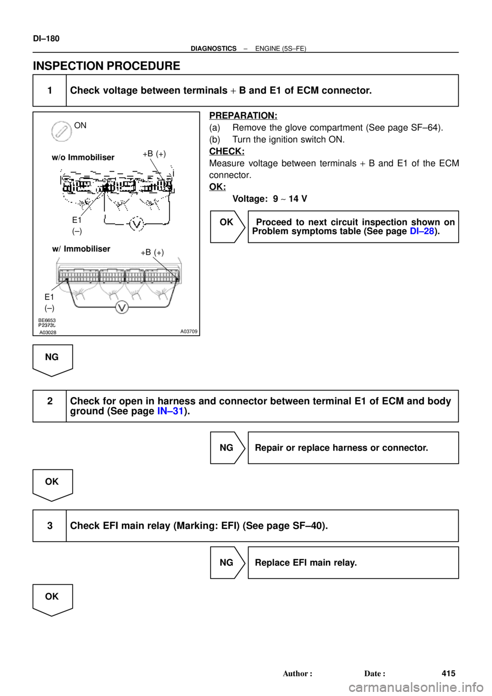
ON
+B (+)
E1
(±)
E1
(±)
+B (+)w/ Immobiliser w/o Immobiliser
DI±180
± DIAGNOSTICSENGINE (5S±FE)
415 Author�: Date�:
INSPECTION PROCEDURE
1 Check voltage between terminals + B and E1 of ECM connector.
PREPARATION:
(a) Remove the glove compartment (See page SF±64).
(b) Turn the ignition switch ON.
CHECK:
Measure voltage between terminals + B and E1 of the ECM
connector.
OK:
Voltage: 9 ~ 14 V
OK Proceed to next circuit inspection shown on
Problem symptoms table (See page DI±28).
NG
2 Check for open in harness and connector between terminal E1 of ECM and body
ground (See page IN±31).
NG Repair or replace harness or connector.
OK
3 Check EFI main relay (Marking: EFI) (See page SF±40).
NG Replace EFI main relay.
OK
Page 1393 of 4592
A00355
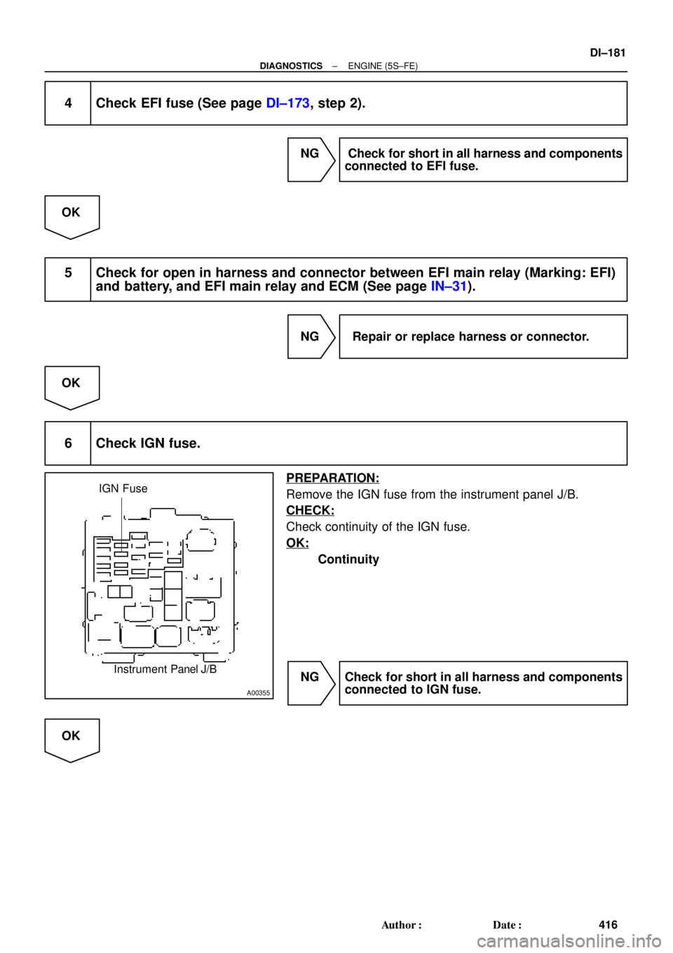
IGN Fuse
Instrument Panel J/B
± DIAGNOSTICSENGINE (5S±FE)
DI±181
416 Author�: Date�:
4 Check EFI fuse (See page DI±173, step 2).
NG Check for short in all harness and components
connected to EFI fuse.
OK
5 Check for open in harness and connector between EFI main relay (Marking: EFI)
and battery, and EFI main relay and ECM (See page IN±31).
NG Repair or replace harness or connector.
OK
6 Check IGN fuse.
PREPARATION:
Remove the IGN fuse from the instrument panel J/B.
CHECK:
Check continuity of the IGN fuse.
OK:
Continuity
NG Check for short in all harness and components
connected to IGN fuse.
OK
Page 1394 of 4592
DI±182
± DIAGNOSTICSENGINE (5S±FE)
417 Author�: Date�:
7 Check ignition switch (See page BE±14).
NG Replace ignition switch.
OK
Check for open in harness and connector between IG switch and EFI main relay, and EFI main
relay and body ground (See page IN±31).
Page 1395 of 4592
A00325
BatteryMAIN IG Switch
AM2EFI
MAIN
FLStarter ST RelayPark/Neutral Position Switch
(Clutch Start Switch)EFI RelayCIR OPN Relay
Fuel Pump
ECM
FC
Tr
STA
NE (STA Signal)
(NE Signal) IGN
STARTER ST
± DIAGNOSTICSENGINE (5S±FE)
DI±183
418 Author�: Date�:
Fuel Pump Control Circuit
CIRCUIT DESCRIPTION
In the diagram below, when the engine is cranked, current flows from terminal ST of the ignition switch to
the starter relay coil and also current flows to terminal STA of ECM (STA signal).
When the STA signal and NE signal are input to the ECM, Tr is turned ON, current flows to coil of the circuit
opening relay, the relay switches on, power is supplied to the fuel pump and the fuel pump operates.
While the NE signal is generated (engine running), the ECM keeps Tr ON (circuit opening relay ON) and the
fuel pump also keeps operating.
DI01M±05


EFI RelayCIR OPN Relay
Fuel Pump
ECM
FC
Tr
STA
NE (STA Signal)
(NE Signal) IGN
STARTER ST
�")